_E01_434_Q01.png)
A
B
C
D
Text Solution
Verified by Experts
The correct Answer is:


Topper's Solved these Questions
ELECTRONIC DEVICES
MTG GUIDE|Exercise CHECK YOUR BEET VITALS|25 VideosELECTRONIC DEVICES
MTG GUIDE|Exercise AIPMT/NEET (MCQs)|42 VideosELECTRONIC DEVICES
MTG GUIDE|Exercise AIPMT/NEET (MCQs)|42 VideosELECTROMAGNETIC WAVES
MTG GUIDE|Exercise AIPMT/NEET(MCQs)|15 VideosELECTROSTATICS
MTG GUIDE|Exercise AIPMT/NEET (MCQ.s)|34 Videos
Similar Questions
Explore conceptually related problems
MTG GUIDE-ELECTRONIC DEVICES-NEET CAFÉ (TOPICWISE PRACTICE QUESTIONS)
- Which of the following gates (figure) will have an output of 1 ?
Text Solution
|
- The combination of the gates as shown in figure represent
Text Solution
|
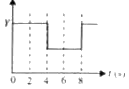
- The real time variation of input signals A and B are as shown below. I...
Text Solution
|
- Identify the logic operation performed by the circuit as shown in the ...
Text Solution
|
- In the circuit below, A and B represent two inputs and C represents th...
Text Solution
|
- In the Boolean algebra, what is the equivalent expression for barA.bar...
Text Solution
|
- The inputs and outputs for different time intervals are given below fo...
Text Solution
|
- The Boolean equation for the circuit given in figure is
Text Solution
|
- Select the outputs Y of the combination of gates shown below for input...
Text Solution
|
- Which logic gate is represented by the following combination of logic ...
Text Solution
|
- The circuit as shown in the figure is equivalent to
Text Solution
|
- The logic circuit shown below has the input waveforms A and B as shown...
Text Solution
|
- The output Y of the logic circuit as shown in figure is
Text Solution
|
- NAND gates can be used to form AND gate. What is the the minimum numbe...
Text Solution
|
- The circuit as shown in figure is equivalent to
Text Solution
|
- The simplified Y output of the given logic circuit is
Text Solution
|
- In Boolean algebra bar((A+barB))*C will be equal to
Text Solution
|
- The circuit as shown in figure is equivalent to
Text Solution
|
- The output Y of the logic circuit as shown in figure is best represent...
Text Solution
|
- The combination of the gates shown below yields
Text Solution
|