
A
B
C
D
Text Solution
Verified by Experts
The correct Answer is:


Topper's Solved these Questions
ELECTRONIC DEVICES
MTG GUIDE|Exercise CHECK YOUR BEET VITALS|25 VideosELECTRONIC DEVICES
MTG GUIDE|Exercise AIPMT/NEET (MCQs)|42 VideosELECTRONIC DEVICES
MTG GUIDE|Exercise AIPMT/NEET (MCQs)|42 VideosELECTROMAGNETIC WAVES
MTG GUIDE|Exercise AIPMT/NEET(MCQs)|15 VideosELECTROSTATICS
MTG GUIDE|Exercise AIPMT/NEET (MCQ.s)|34 Videos
Similar Questions
Explore conceptually related problems
MTG GUIDE-ELECTRONIC DEVICES-NEET CAFÉ (TOPICWISE PRACTICE QUESTIONS)
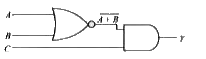
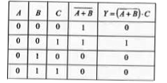
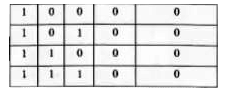
- The Boolean equation for the circuit given in figure is
Text Solution
|
- Select the outputs Y of the combination of gates shown below for input...
Text Solution
|
- Which logic gate is represented by the following combination of logic ...
Text Solution
|
- The circuit as shown in the figure is equivalent to
Text Solution
|
- The logic circuit shown below has the input waveforms A and B as shown...
Text Solution
|
- The output Y of the logic circuit as shown in figure is
Text Solution
|
- NAND gates can be used to form AND gate. What is the the minimum numbe...
Text Solution
|
- The circuit as shown in figure is equivalent to
Text Solution
|
- The simplified Y output of the given logic circuit is
Text Solution
|
- In Boolean algebra bar((A+barB))*C will be equal to
Text Solution
|
- The circuit as shown in figure is equivalent to
Text Solution
|
- The output Y of the logic circuit as shown in figure is best represent...
Text Solution
|
- The combination of the gates shown below yields
Text Solution
|
- The circuit diagram (see fig.) shows a 'logic combination' with the st...
Text Solution
|
- In the circuit givne, A, B and C are inputs and Y is the output. ...
Text Solution
|
- Which of the following truth tables corresponds to NAND gate ?
Text Solution
|
- The output of given logic circuit is
Text Solution
|
- The output y, when all three inputs are first high and then low, will ...
Text Solution
|
- The logic gates giving output '1' for the inputs of '1' and '0' are
Text Solution
|
- The truth table for the following logic circuit is
Text Solution
|