A
B
C
D
Text Solution
Verified by Experts
The correct Answer is:


Topper's Solved these Questions
Similar Questions
Explore conceptually related problems
MTG GUIDE-ELECTRONIC DEVICES-CHECK YOUR BEET VITALS
- Which of the following elements when added as an impurity into the ger...
Text Solution
|
- At temperature of absolute zero an intrinsic semiconductor is
Text Solution
|
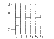
- The figure shows the voltage waveforms across two inputs A and B and t...
Text Solution
|
- In an n-p-n transistor amplifier, the collector current is 9 mA. If 90...
Text Solution
|
- A 220 V ac supply is connected between points A and B as shown 220 V i...
Text Solution
|
- If the energy gap between valence band and conduction band is 10 eV, t...
Text Solution
|
- SSI integrated chip contains
Text Solution
|
- In the figure, the input waveform is converted into the output wavefor...
Text Solution
|
- The input resistance of a silicon transisitor is 100Omega. Base curren...
Text Solution
|
- Match List I with List II and select the correct answer using the code...
Text Solution
|
- The amplifiers X, Y and Z are connected in series. The voltage gain of...
Text Solution
|
- Four photodiodes D(1), D(2),D(3) and D(4) are made of semiconductors h...
Text Solution
|
- In the circuit, the current flowing through the zener diode is
Text Solution
|
- Of the diodes shown in the following diagrams, which one is reverse bi...
Text Solution
|
- The current in the circuit will be
Text Solution
|
- In the case of forward biasing of PN-junction, which one of the follow...
Text Solution
|
- p-n junction is called as forward biased when
Text Solution
|
- The transfer ratio (beta) of a transistor is 50. The input resistance...
Text Solution
|
- When the emitter current of a transistor is changed by 1 mA, its colle...
Text Solution
|
- In a transistor, the current amplification factor alpha is 0.9. The tr...
Text Solution
|