Home
Class 12
PHYSICS
The phase relationship between current a...

The phase relationship between current and voltage in a pure resistive circuit is best represented by

A

B

C

D

Text Solution

AI Generated Solution

The correct Answer is:
To determine the phase relationship between current and voltage in a pure resistive circuit, we can follow these steps: ### Step-by-Step Solution: 1. **Understand the Components of the Circuit**: - In a pure resistive circuit, the only component present is a resistor connected to an AC voltage source. 2. **Voltage and Current Equations**: - The voltage across the resistor can be expressed as: \[ V(t) = V_0 \sin(\omega t) \] - The current flowing through the resistor can be expressed as: \[ I(t) = I_0 \sin(\omega t) \] 3. **Identify the Phase Relationship**: - Both the voltage and current equations have the same angular frequency (\(\omega\)) and the same time variable (\(t\)). This indicates that the voltage and current reach their maximum and minimum values at the same time. 4. **Determine Phase Difference**: - Since both the voltage and current waveforms are represented by the same sine function, the phase difference (\(\phi\)) between them is: \[ \phi = 0 \] - This means that the voltage and current are in phase. 5. **Graphical Representation**: - If we were to draw the waveforms for both voltage and current, they would oscillate together, reaching their peaks and troughs simultaneously. The voltage waveform would have a peak value of \(V_0\) and the current waveform would have a peak value of \(I_0\). 6. **Conclusion**: - In a pure resistive circuit, the phase relationship between current and voltage is such that they are in phase, which can be summarized as: \[ \text{Phase difference } \phi = 0 \] ### Final Answer: The phase relationship between current and voltage in a pure resistive circuit is best represented by the fact that they are in phase, meaning the phase difference is \(0\). ---

To determine the phase relationship between current and voltage in a pure resistive circuit, we can follow these steps: ### Step-by-Step Solution: 1. **Understand the Components of the Circuit**: - In a pure resistive circuit, the only component present is a resistor connected to an AC voltage source. 2. **Voltage and Current Equations**: ...
Promotional Banner

Topper's Solved these Questions

  • ALTERNATING CURRENT

    NCERT FINGERTIPS ENGLISH|Exercise HOTS|8 Videos
  • ALTERNATING CURRENT

    NCERT FINGERTIPS ENGLISH|Exercise NCERT|7 Videos
  • ATOMS

    NCERT FINGERTIPS ENGLISH|Exercise Assertion And Reason|15 Videos

Similar Questions

Explore conceptually related problems

The phase angle between current and voltage in a purely inductive circuit is

In a purely resistive AC circuit,

Phase relationship between current (l) and applied voltage (E) for a series LCR circuit is shown here. omega_(0) = Resonant angular frequency of the circuit and omega = Applied angular frequency .

A resistance is connected to a capacitor in AC are the phase differece is (pi)/(4) between current and voltage. Whe the same resistance is connected to an inductor, phase difference becomes tan^(-1)(2) . Power factor of the circuit when both capacitor and inductor are connect to the resistance will be

(i) Find the value of the phase difference between the current and the voltage in the series LCR circuit shown below. Which one leads in phase : current or voltage ? (ii) What making any other change, find the value of the additional capacitor C, to be connected in parallel with the capacitor C, in order to make the power factor of the circuit unity.

An ac source of voltage V=V_(m)sin omega t is connected across the resistance R as shown in figure. The phase relation between current and voltage for this circuit is

A seriesLCR circuit is connected to an ac voltage source. When L is removed from the circuit, the phase difference between current and voltage is pi/3 . If instead C is removed from the circuit phase difference is again pi/3 between current and voltage. Power factor of circuit is:

An alternating emf 200 volts at 50 Hz is connected to a circuit resistance 1ohm and inductance 0.01 H . What is the phase difference between the current and the emf in the circuit? Also, find the current in the circuit.

An alternating emf 200 virtual volts at 50 Hz is connected to a circuit resistance 1Omega and inductance 0.01 H . What is the phase difference between the current and the emf in the circuit? Also, find the virtual current in the circuit.

The phase difference between voltage and current in series L-C circuit is

NCERT FINGERTIPS ENGLISH-ALTERNATING CURRENT -Assertion And Reason
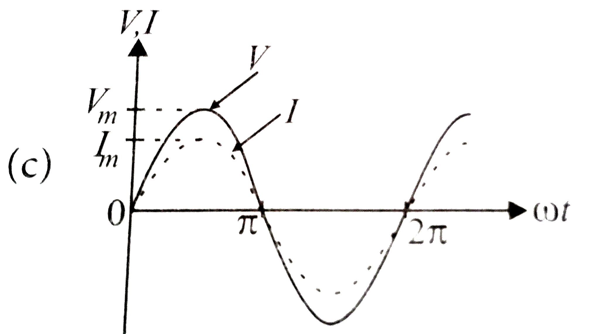
  1. The phase relationship between current and voltage in a pure resistive...

    Text Solution

    |

  2. Assertion : An alternating current does not show any magnetic effect. ...

    Text Solution

    |

  3. Assertion: Average value of AC over a complete cycle is always zero. ...

    Text Solution

    |

  4. Assertion : The capacitive reactance limits the amplitude of the curre...

    Text Solution

    |

  5. Assertion : The inductive reactance limits amplitude of the current in...

    Text Solution

    |

  6. Assertion : In series LCR resonance circuit, the impedance is equal to...

    Text Solution

    |

  7. Assertion : In a purely inductive or capacitive circuit, the current i...

    Text Solution

    |

  8. Assertion : The only element that dissipates energy in an ac circuit i...

    Text Solution

    |

  9. Assertion : The power in ac circuit is minimum if the circuit has only...

    Text Solution

    |

  10. Assertion : Resonance is exhibited by a circuit only if both L and C a...

    Text Solution

    |

  11. Assertion : When a current flows in the coil of a transformer then its...

    Text Solution

    |

  12. Assertion : An ideal transformer does not vary the power. Reason : A...

    Text Solution

    |

  13. Assertion : A step-up transformer changes a low voltage into a high vo...

    Text Solution

    |

  14. Assertion : A given transformer can be used to step-up ot step-down th...

    Text Solution

    |

  15. Assertion : A laminated core is used in transformers to increase eddy ...

    Text Solution

    |

  16. Assertion : A transformer cannot work on dc supply. Reason : dc chan...

    Text Solution

    |