Home
Class 12
PHYSICS
The circuit shown in the figure contains...

The circuit shown in the figure contains two diodes each with a forward resistance of 30 `Omega` and with infinite backward resistance. If the battery is 3 V, the current through the 50 `Omega` resistance (in ampere) is

A

zero

B

0.01

C

0.02

D

0.03

Text Solution

Verified by Experts

The correct Answer is:
C

In the circuit the upper diode `D_1` is reverse biased and the lower diode `D_2` is forward biased. Thus there will be no current across upper diode junction. The effective circuit will be as shown in figure.
Total resistance of circuit, R = 50 + 70 + 30 = 150 `Omega`
Current in circuit, `I=V/R=(3V)/(150 Omega)=0.02 A`
Promotional Banner

Topper's Solved these Questions

  • SEMICONDUCTOR ELECTRONICS : MATERIALS , DEVICES AND SIMPLE CIRCUITS

    NCERT FINGERTIPS ENGLISH|Exercise HOTS|8 Videos
  • SEMICONDUCTOR ELECTRONICS : MATERIALS , DEVICES AND SIMPLE CIRCUITS

    NCERT FINGERTIPS ENGLISH|Exercise NCERT|8 Videos
  • RAY OPTICS AND OPTICAL INSTRUMENTS

    NCERT FINGERTIPS ENGLISH|Exercise NCERT Exemplar|11 Videos
  • WAVE OPTICS

    NCERT FINGERTIPS ENGLISH|Exercise Assertion And Reason|15 Videos

Similar Questions

Explore conceptually related problems

The circuit shown in figure (1) Contains two diodes each with a forward resistance of 50 ohm and with infinite reverse resistance. If the battery voltage is 6 V , the current through the 100 ohm resistance is. .

The circuit shown in the figure contains two diodes each with a forward resistance of 50Omega and with infinite backward resistance. If the batter of 6 V is connected in the circuit, then the current through the 100 Omega resistance is

The circuit shown in figure contains two diodes each with a forward resistance of 50Ω and infinite reverse resistance.If the battery voltage is 6 v ,then the current through the 100Ω resistance is

The circuit showm below contains two ideal diodes, each with a forward resistance of 50 Omega . If the battery voltage is 6 V, the current through the 100 Omega resistance ( in Amperes) is:

Current passing through 3 Omega resistance is

In the circuit, the current flowing through 10Omega resistance is

In the circuit in figure, the current flowing 5 Omega resistance is :

Find the current l through then 10 Omega resistance in the network shown in figure.

In the given circuit current flowing through 2 Omega resistance is

Find the current through the resistance in the circuits shown in figure

NCERT FINGERTIPS ENGLISH-SEMICONDUCTOR ELECTRONICS : MATERIALS , DEVICES AND SIMPLE CIRCUITS -Assertion And Reason
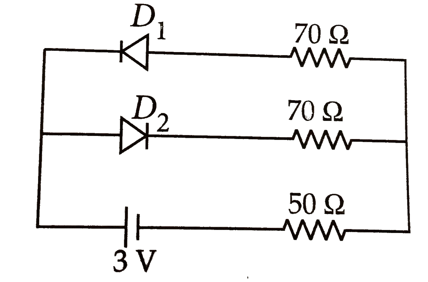
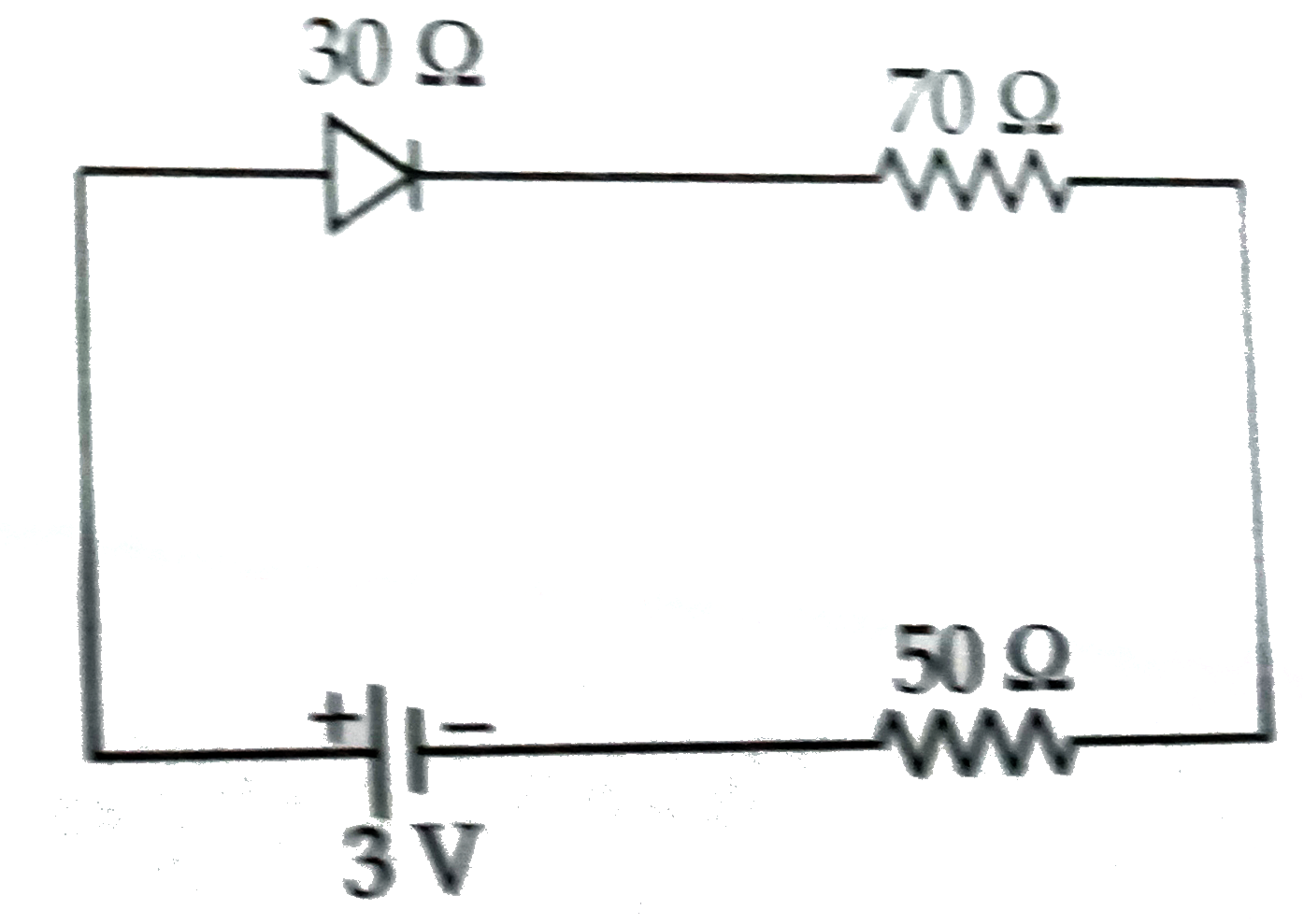
  1. The circuit shown in the figure contains two diodes each with a forwar...

    Text Solution

    |

  2. Assertion: If there is some gap between the conduction band and the va...

    Text Solution

    |

  3. Assertion : The electrons in the conduction band have higher energy th...

    Text Solution

    |

  4. Assertion : In a semiconductor, the conduction electrons have a higher...

    Text Solution

    |

  5. Assertion: The probability of electrons to be found in the conduction ...

    Text Solution

    |

  6. Assertion: The conductivity of an intrinsic semiconductor depends on i...

    Text Solution

    |

  7. Assertion: The conductivity of an intrinsic semiconductor depends on i...

    Text Solution

    |

  8. Assertion: Thickness of depletion layer is fixed in all semiconductor ...

    Text Solution

    |

  9. Assertion: Zener diode works on aa principle of of breakdown voltage. ...

    Text Solution

    |

  10. Assertion : Zener diode is used to obtain voltage regulation Reason ...

    Text Solution

    |

  11. Assertion: The semiconductor used for fabrication of visible LEDs must...

    Text Solution

    |

  12. Assertion : In a transistor the base is made thin. Reason: A thin b...

    Text Solution

    |

  13. Assertion : Two p-n junction diodes placed back to back, will work as ...

    Text Solution

    |

  14. Assertion : In an oscillator, the feedback is in the same phase which ...

    Text Solution

    |

  15. Assertion : In an OR gate if any of the input is high, the output is h...

    Text Solution

    |

  16. Assertion: This circuit acts as OR Gate. Reason: Truth table for...

    Text Solution

    |