Text Solution
Verified by Experts


Topper's Solved these Questions
SEMICONDUCTOR DEVICES
AAKASH SERIES|Exercise Exercise (Long answer questions)|3 VideosSEMICONDUCTOR DEVICES
AAKASH SERIES|Exercise Exercise (Short answer questions)|10 VideosRAY OPTICS
AAKASH SERIES|Exercise PROBLEMS ( LEVEL-II)|50 VideosUNITS AND MEASUREMENT
AAKASH SERIES|Exercise PRACTICE EXERCISE|45 Videos
Similar Questions
Explore conceptually related problems
AAKASH SERIES-SEMICONDUCTOR DEVICES-EXERCISE - II
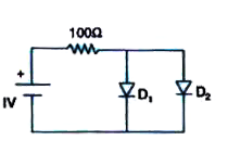
- Considering the circuit and data given in the diagram calculate the cu...
Text Solution
|
- A full-wave p-n diode rectifier uses a load resistor of 1500Omega. No ...
Text Solution
|
- A p-n junction (D) shown in the figure can act as a rectifier. An alte...
Text Solution
|
- The input signal given to a CE amplifier having a voltage gain of 150 ...
Text Solution
|
- In the figure shown, the currents through the series resistance and lo...
Text Solution
|
- The value of the resistor, R(s), needed in the de voltage regulator ci...
Text Solution
|
- The current gain of a transistor in common base and common-emitter con...
Text Solution
|
- For a transistor, the value of alpha= 0.9, then the value of B is
Text Solution
|
- The current gain in common-base configuration of n-p-n transistor is 0...
Text Solution
|
- For a transistor, the current gain of common- base configuration is 0....
Text Solution
|
- Calculate the current amplification factor beta when change in collect...
Text Solution
|
- A change of 200mV in base-emitter voltage causes a change of 100muA in...
Text Solution
|
- The emitter current in a transistor is 2.2mA and the collector current...
Text Solution
|
- While a collector-emitter voltage is constant in a transistor, the col...
Text Solution
|
- If in a transistor if (I(C))/(I(E))=alpha and (I(C))/(I(B))=beta , If ...
Text Solution
|
- Which of the following logic gates the given truth table represents
Text Solution
|
- Which of the following logic gates the given truth table represents
Text Solution
|
- The logic symbol shown in figure represents
Text Solution
|
- The arrangement shown in figure performs the logic function of
Text Solution
|
- The name of the gate obtained by the combination as shown is
Text Solution
|
- Given below are four logic gate symbols. Those for OR, NOR and AND are...
Text Solution
|