Text Solution
Verified by Experts


Topper's Solved these Questions
SEMICONDUCTOR DEVICES
AAKASH SERIES|Exercise Problems (LEVEL-II)|7 VideosSEMICONDUCTOR DEVICES
AAKASH SERIES|Exercise EXAMPLES|56 VideosSEMICONDUCTOR DEVICES
AAKASH SERIES|Exercise Exercise (very Short answer questions)|11 VideosRAY OPTICS
AAKASH SERIES|Exercise PROBLEMS ( LEVEL-II)|50 VideosUNITS AND MEASUREMENT
AAKASH SERIES|Exercise PRACTICE EXERCISE|45 Videos
Similar Questions
Explore conceptually related problems
AAKASH SERIES-SEMICONDUCTOR DEVICES-Problems (LEVEL-I)
- Find the static resistance of a P-N junction germanium diode if temper...
Text Solution
|
- In a p-n junction diode made with Ge, the thickness of depletion layer...
Text Solution
|
- A potential barrier of 0.3V exists across a P-N junction (a) If the de...
Text Solution
|
- A junction diode is connected to an external resistance of 100Omega an...
Text Solution
|
- The junction diode shown in figure is ideal. Find the current in the c...
Text Solution
|
- Determine the current through a silicon diode of (barrier potential = ...
Text Solution
|
- Find the current in the circuit shown below
Text Solution
|
- Calculate the current flowing in the circuit below which has two oppos...
Text Solution
|
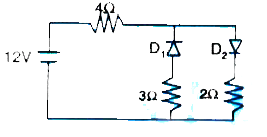
- The circuit shown below contains two diodes, each of forward resistanc...
Text Solution
|
- An ideal p-n junction diode can withstand currents up to 10mA under fo...
Text Solution
|
- The resistance of the diode in the forward biased condition is 200Omeg...
Text Solution
|
- Find maximum voltage across AB in the circuit shown in figure. Assume ...
Text Solution
|
- A diode used in the circuit shown in fig. below, has a constant voltag...
Text Solution
|
- For the circuit shown in Fig. find 1) the output voltage 2) the vo...
Text Solution
|
- For a transistor a = 0.98 and emitter current I(E) = 2.5 mA. Calculate...
Text Solution
|
- In common base configuration of a transistor, a change of 200 mV in em...
Text Solution
|
- In a transistor the emitter current is 1.01 times as large as the coll...
Text Solution
|
- A change of 0.5 mA in the emitter current of a transistor produces a c...
Text Solution
|
- A change of 200mV in base-emitter voltage causes a change of 1004A in ...
Text Solution
|
- AP-N-P transistor is used in common-emitter mode in an amplifier circu...
Text Solution
|