Text Solution
Verified by Experts


Topper's Solved these Questions
Similar Questions
Explore conceptually related problems
KUMAR PRAKASHAN-CONTROL AND COORDINATION-PRACTICAL SKILL BASED QUESTIONS WITH ANSWERS
- Four different students of your class observed network of neurons in a...
Text Solution
|
- Four different students of your class observed network of neurons in a...
Text Solution
|
- Four different students of your class observed network of neurons in a...
Text Solution
|
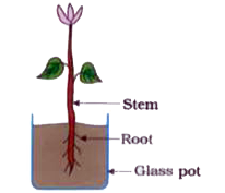
- Your subject teacher arranged a potted plant as shown in figure (a). N...
Text Solution
|
- Your subject teacher arranged a potted plant as shown in figure (a). N...
Text Solution
|
- Your subject teacher arranged a potted plant as shown in figure (a). N...
Text Solution
|
- Your subject teacher arranged a potted plant as shown in figure (a). N...
Text Solution
|
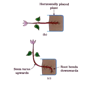
- Observe figs. (a), (b), (c) and (d). rarr Determine on the basis of ...
Text Solution
|