Text Solution
Verified by Experts


Topper's Solved these Questions
ALTERNATING CURRENTS
KUMAR PRAKASHAN|Exercise SECTION-C NCERT EXEMPLAR ( Short Answer)|6 VideosALTERNATING CURRENTS
KUMAR PRAKASHAN|Exercise SECTION-C NCERT EXEMPLAR (Long Answer)|5 VideosALTERNATING CURRENTS
KUMAR PRAKASHAN|Exercise SECTION-C NCERT EXEMPLAR (More than one Options)|6 VideosATOMS
KUMAR PRAKASHAN|Exercise Section-D -MCQs asked in GUJCET / Board Exam|34 Videos
Similar Questions
Explore conceptually related problems
KUMAR PRAKASHAN-ALTERNATING CURRENTS -SECTION-C NCERT EXEMPLAR (Very Short Answer)
- If a LC circuit is considered analogous to a harmonically oscillating ...
Text Solution
|
- Draw the effective equivalent circuit of the circuit shown in figure a...
Text Solution
|
- Study the circuits (a) and (b) shown in figure and answer the followin...
Text Solution
|
- Can the instantaneous power output of an ac source ever be negative ? ...
Text Solution
|
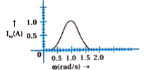
- In series LCR circuit, the plot of I"max" vs omega as shown in figure....
Text Solution
|
- The alternating current in a circuit is described by the graph shown i...
Text Solution
|
- How does the sign of the phase angle phi, by which the supply voltage ...
Text Solution
|