A
B
C
D
Text Solution
Verified by Experts
The correct Answer is:


Topper's Solved these Questions
Similar Questions
Explore conceptually related problems
KUMAR PRAKASHAN-ALTERNATING CURRENTS -SECTION-D MCQs (DARPAN BASED ON TEXTBOOK)
- A resistor 30Omega, inductor of reactance 10Omega and capacitor of rea...
Text Solution
|
- An inductance of 1 mH, a condenser of 10 muF and a resistance of 50 Om...
Text Solution
|
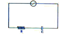
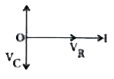
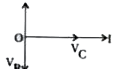
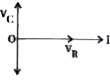
- Phasor diagram for the following circuit ……..
Text Solution
|
- Phasor diagram for the following circuit is …….
Text Solution
|
- Phasor diagram for the following circuit is …….
Text Solution
|
- In an A.C. series circuit of L-R voltage applied is 220 V, if the pote...
Text Solution
|
- In series L-C-R circuit, resistance, inductance and capacitance are co...
Text Solution
|
- A coil of resistance R and inductance L is joined with a battery of E ...
Text Solution
|
- In a given circuit V = 5V, VL = 3V then VR=
Text Solution
|
- A pure resistance and a pure inductance are connected in series across...
Text Solution
|
- If we consider the phasor if I in positive X-direction for an A.C. cir...
Text Solution
|
- When above circuit is in the condition of resonance,
Text Solution
|
- Reading in voltmeter in above circuit is......
Text Solution
|
- Voltage V1 across the capacitor in above circuit is
Text Solution
|
- In Phasor's method, magnitude (or length) of vector (known as Phasor) ...
Text Solution
|
- Phasor's method is used for ……..
Text Solution
|
- If in an A.C. L-C series circuit XL gt XC . Hence current …….
Text Solution
|
- An A.C. source is connected to a resistive circuit, current …….
Text Solution
|
- The relation between the phase of current and voltage in a circuit con...
Text Solution
|
- In an A.C. circuit the value of inductive reactance connected with it,...
Text Solution
|