Home
Class 12
PHYSICS
The inputs to the digital circuit are sh...

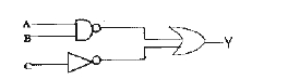
The inputs to the digital circuit are shown below. The output Y is

A

`A +B+bar(C )`

B

`(A + B) bar(C )`

C

`bar(A) + bar(B) + bar(C)`

D

`bar(A) + bar(B) + C`

Text Solution

Verified by Experts

Promotional Banner

Topper's Solved these Questions

  • QUESTION PAPER 2015

    WB JEE PREVIOUS YEAR PAPER|Exercise PHYSICS (CATEGORY II)|4 Videos
  • QUESTION PAPER 2015

    WB JEE PREVIOUS YEAR PAPER|Exercise PHYSICS (CATEGORY III)|5 Videos
  • QUESTION PAPER 2014

    WB JEE PREVIOUS YEAR PAPER|Exercise PHYSICS (CATEGORY III)|3 Videos
  • QUESTION PAPER 2016

    WB JEE PREVIOUS YEAR PAPER|Exercise PHYSICS|40 Videos

Similar Questions

Explore conceptually related problems

In the circuit shown

The output of the logic circuit given below is

The output of the given circuit in Fig 1.53.

Derive an expression for voltage gain of the amplifier and hence show that the output voltage is in opposite phase with the input voltage.

The current l in the circuit shown is

Find the value of the phase difference between the current and the voltage in the series LCR circuit shown below. Which one leads in phase:current or voltage?

Statement I : In CE mode of a transistor if the input signal is applied at base then the output signal is obtained at collector. Statement II : In a transistor most of the emitter current is transformed into the collector current.

ExpIain why the input resistance of a transistor is Iow whiIe the output resistance is high.

Transformer is a device used to increase or decrease the voltage in the transmission line according to requirement, Generally the input line voltage is fed in a primary coil and the output line voltage is obtained from the terminals of another coil In an ideal transformer, the primary and secondary coils are linked is such a way that there is no loss of magnetic flux and electrical energy. In an ideal transformer, if the number of turns and input voltage across the terminals of the primary coils be N_1 and V_1 , then the output voltage at the two terminals of the secondary coil V_2=V_1.N_2/N_1 , where N_2 is the number of turns in the secondary coil . In question (i) if the input power of the transformer be 44 W, then output power is