Home
Class 12
PHYSICS
In the circuit shown in figure find ...

In the circuit shown in figure find

a. the equivalent capacitance
b. the charge stored in each capacitor and
c. the potential difference across each capacitor.

Text Solution

Verified by Experts

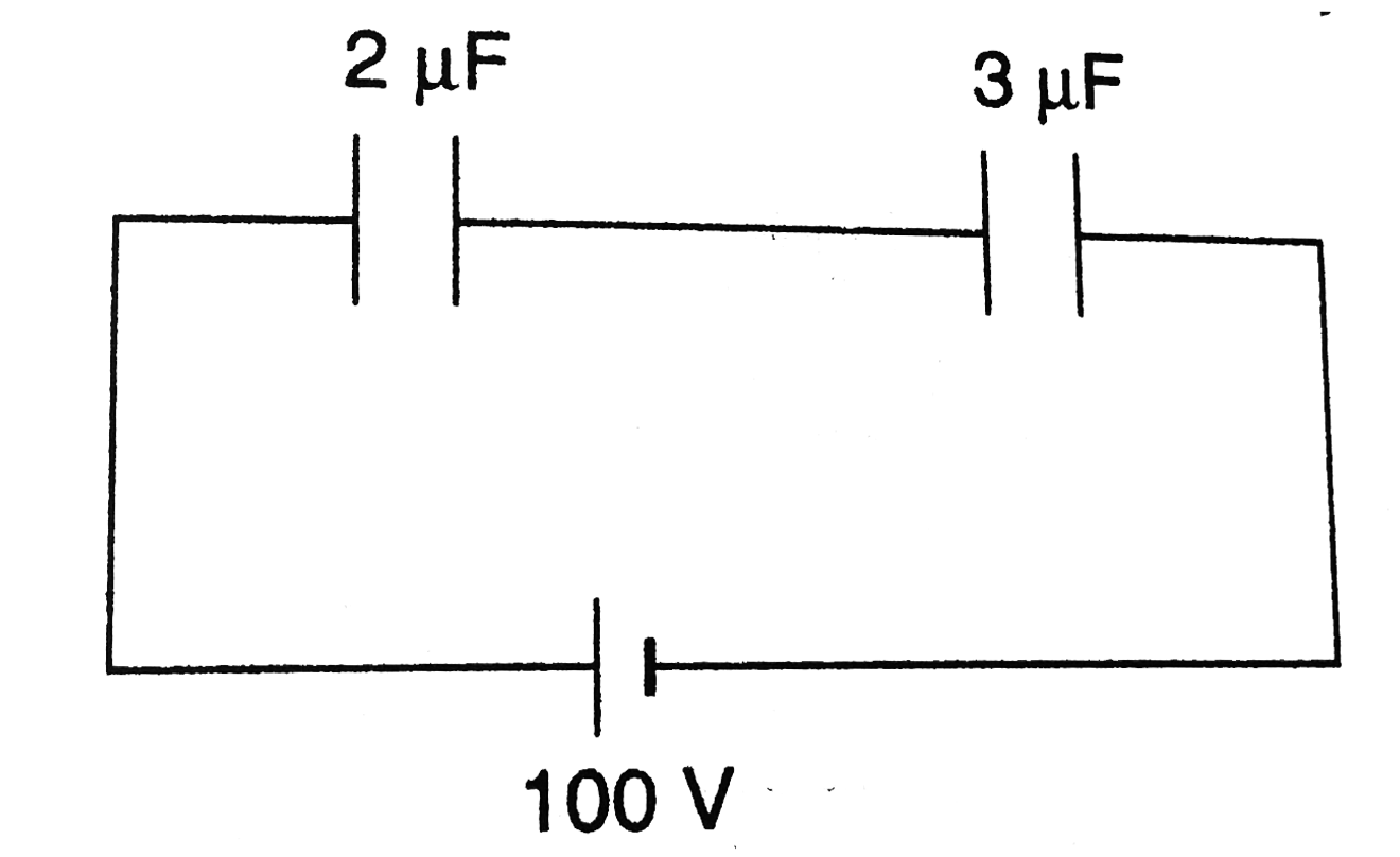
a. The equivalent capacitance
`C=(C_1C_2)/(C_1+C_2)`
or `C=((2)(3))/(2+3)=1.2muF`

b. The charge `q` stored in each capacitor is
`q=CV=(1.2xx10^-6)(100)C`
`=120muC`
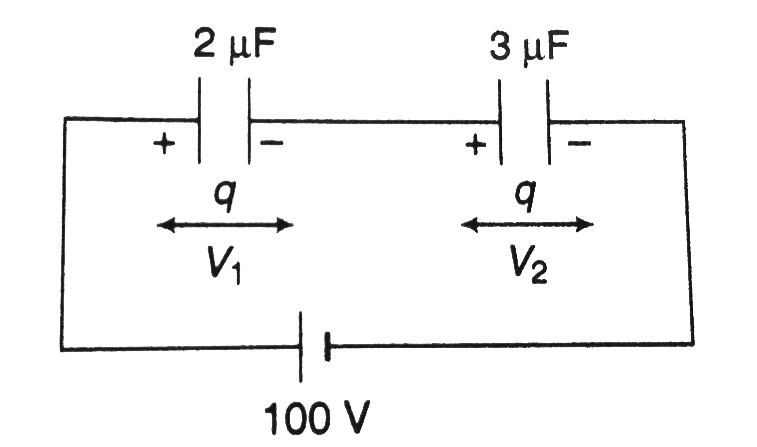
c. In series combination `Vprop1/C or V_1/V_2=C_2/C_1`
`:. V_1=(C_2/(C_1+C_2))V+((3)/(2+3))(100)=60V`
`and V_2=V-V_1 =100-60=40V` ltbr In parallel

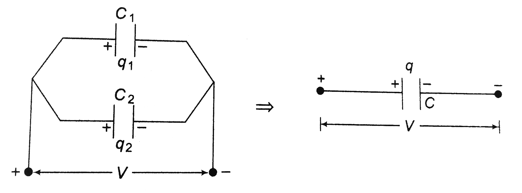
the arrangement shown in figure is called a paralel connection. In a parallel combination the potential difference for all individual capacitors is the same and the total charge `q` is distributed in the ratio of the capacities. (as`q=CV` or `qpropC` for same potential difference). Thus,
`q_1/q_2=C_1/C_2`
or `q_1=((C_1)/(C_1+C_2))q and q_2=((C_2)/(C_1+C_2))q`
The parallel combination is equivalent to a single capacitor with the same total charge `q=q_1+q_2` and potential difference V.
Thus,
`q=q_1+q_2`
or `CV=C_1+C_2V`
or `C=C_1+C_2`
In the same way, we can show that for any number of capacitors in parallel
`C=C-1+C_2+C_3+..........`
In a parallel combination the equilavent capacitance is always greater than any individual capacitance.
Promotional Banner

Topper's Solved these Questions

  • CAPACITORS

    DC PANDEY ENGLISH|Exercise Exercise|155 Videos
  • CAPACITORS

    DC PANDEY ENGLISH|Exercise OBJECTIVE_TYPE|1 Videos
  • ATOMS

    DC PANDEY ENGLISH|Exercise MEDICAL ENTRANCES GALLERY|42 Videos
  • COMMUNICATION SYSTEM

    DC PANDEY ENGLISH|Exercise Subjective|11 Videos

Similar Questions

Explore conceptually related problems

In the circuit shown in figure find a. the equivalent capacitance and b. the charge stored in each capacitor.

In the circuit shown in figure find a. the equivalent capacitance and b. the charge stored in each capacitor.

In the circuit shown in figure find a. the equivalent capacitance and b. the charge stored in each capacitor.

Find charge on each capacitor and potential difference across each capacitor .

Find the potential difference and charge on each capacitor.

In figure C_1=C_5=8.4muF and C_2=C_3=C_4=4.2muF .The applied potential is V_(ab)=220V (a) What is the equivalent capacitance of the network between points a and b ? (b) Calculate the charge on each capacitor and the potential difference across each capacitor.

In the circuit shown in the figure, the potential difference across the 4.5 muF capacitor is

Find the equivalent capacitance between A and B. All the capacitors have capacitance C.

Find the equivalent capacitance between A and B. All the capacitors have capacitance C.

For the circuit shown in the figure, find the charge stored on capacitor in steady state.