Home
Class 12
PHYSICS
Two cellls, two resistance and two capac...

Two cellls, two resistance and two capacitors are connected as shown in figure. The charge on `2muF` capacitors is

A

`30muC`

B

`20muC`

C

`25muC`

D

`48muC`

Text Solution

Verified by Experts

The correct Answer is:
A

Applying Kirchoff's loop law in outermost loop, we have
`-q/3+15-2xx2.5-q/2-3xx1+18=0`
solving this equation we get
Promotional Banner

Topper's Solved these Questions

  • CAPACITORS

    DC PANDEY ENGLISH|Exercise OBJECTIVE_TYPE|1 Videos
  • CAPACITORS

    DC PANDEY ENGLISH|Exercise OBJECTIVE_TYPE|1 Videos
  • ATOMS

    DC PANDEY ENGLISH|Exercise MEDICAL ENTRANCES GALLERY|42 Videos
  • COMMUNICATION SYSTEM

    DC PANDEY ENGLISH|Exercise Subjective|11 Videos

Similar Questions

Explore conceptually related problems

Three uncharged capacitors A, B and C are connected as shown in the figure. The charge on capacitor B is , the steady state.

Find the charges on 6muF and 4muF capacitors

In the circuit shown in figure, the ratio of charge on 5muF and 2muF capacitor is

Two capacitors of 2muF and 3muF are charged to 150 V and 120 V , respectively. The plates of capacitor are connected as shown in the figure. An uncharged capacitor of capacity 1.5muF falls to the free end of the wire. Then

Two capacitors of 2muF and 3muF are charged to 150 V and 120 V , respectively. The plates of capacitor are connected as shown in the figure. An uncharged capacitor of capacity 1.5muF falls to the free end of the wire. Then

In the circuit shown below, the charge on the 60muF capacitor is

Two identical capacitors A and B are charged to the same potential V and are connected in two circuits at t = 0 as shown in figure. The charge of the capacitors at a time t = CR are respectively -

In the circuit shown in the figure, in steady state: The charge on 5 muF capacitor is

Two capacitors A and B with capacities 3muF and 2muF are charged to a potential difference of 100 V and 180V , respectively. The plates of the capacitors are connected as show in figure with one wire of each capacitor free. The upper plate of A is positive and that of B is negastive. An uncharged 2muF capcitor C with lead wires falls on the free ends to complete the circuit. Calculate a. the final charge on the three capacitors. b. the amount of electrostatic energy stored in the system before and after completion of the circuit.

Several capacitors are connected as shown in. If the charge on the 5 muF capacitor is 120 muC , the potential between points A and D is .

DC PANDEY ENGLISH-CAPACITORS-Exercise
  1. Three uncharged capacitors of capacitance C1,C2 and C3 are connected t...

    Text Solution

    |

  2. In the circuit shown in figure potential difference between the points...

    Text Solution

    |

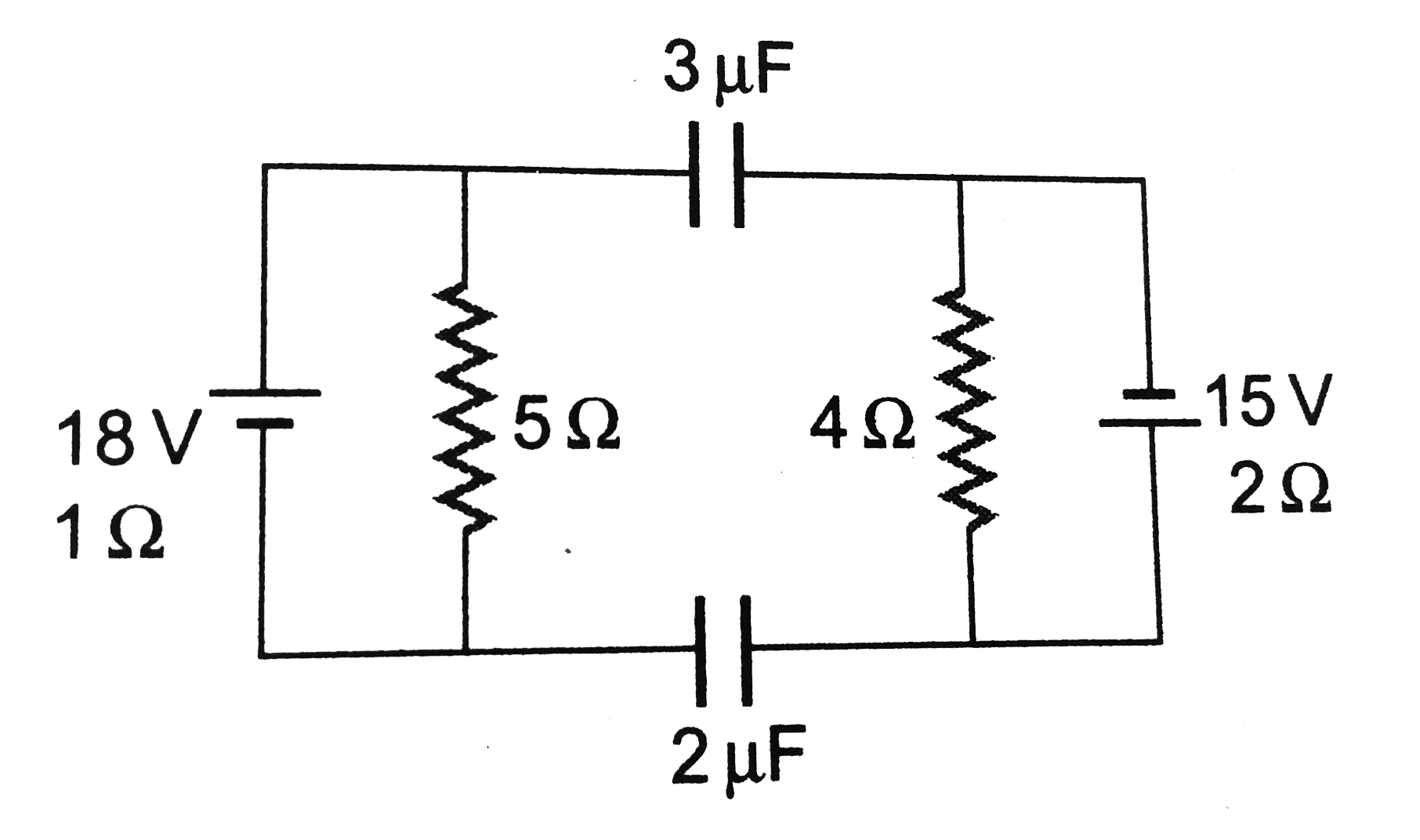
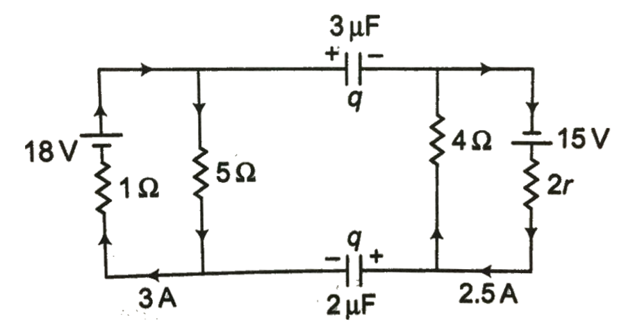
  3. Two cellls, two resistance and two capacitors are connected as shown i...

    Text Solution

    |

  4. In the circuit shown in figure, the capacitor is charged with a cell o...

    Text Solution

    |

  5. The potential difference between points a and b of circuits shown in f...

    Text Solution

    |

  6. A capacitors C1 is charged to a potential V and connected to another c...

    Text Solution

    |

  7. In the circuit diagram the current through the battery immediately aft...

    Text Solution

    |

  8. In the circuit shown switch S is closed at t=0. Let i1 and i2 be the c...

    Text Solution

    |

  9. A charged capacitor is allowed to dischare through a resistor by clos...

    Text Solution

    |

  10. Five identical capacitor plates are arranged such that they make four ...

    Text Solution

    |

  11. A capacitor of capacitance C is charged to a potential difference V fr...

    Text Solution

    |

  12. X and Y are large, parallel conducting plates close to each other. Eac...

    Text Solution

    |

  13. In the circuit shown in the figure, switch S is closed at time t=0. Se...

    Text Solution

    |

  14. An electrical circuit is shown in the given figure. The resistance of ...

    Text Solution

    |

  15. In the circuit shown, A and B are equal resistances. When S is closed,...

    Text Solution

    |

  16. A parallel plate capacitor is charged from a cell and then isolated fr...

    Text Solution

    |

  17. In the circuit shown each capacitor has a capcitance C. The emf of the...

    Text Solution

    |

  18. Two capacitors of 2muF and 3muF are charged to 150 V and 120 V, respec...

    Text Solution

    |

  19. A parallel plate capacitor is charged and then the battery is disconne...

    Text Solution

    |

  20. A capacitor of 2F (practically not possible to have a capacity of 2F) ...

    Text Solution

    |