Home
Class 12
PHYSICS
Two capacitors of 2muF and 3muF are char...

Two capacitors of `2muF` and `3muF` are charged to `150 V` and `120 V`, respectively. The plates of capacitor are connected as shown in the figure. An uncharged capacitor of capacity `1.5muF` falls to the free end of the wire. Then

A

chargeg on `1.5muF` capacitor is `180 muF`

B

charge on `2muF `capacitor is `120muF`

C

positive chasrge flows through A from right to left

D

positive charge flows through A from left to right

Text Solution

Verified by Experts

The correct Answer is:
A, B, D

Let `(+q)muC` charge flows in the closed loop in clockwise direction. Then final charge on different capatiors we as shown in figure.
Now, applying Kirchoff's loop law
`(360-q)/3+(300-q)/2=q/1.5`
Solving the abvoe equation we get
`q=180muC`
Promotional Banner

Topper's Solved these Questions

  • CAPACITORS

    DC PANDEY ENGLISH|Exercise OBJECTIVE_TYPE|1 Videos
  • CAPACITORS

    DC PANDEY ENGLISH|Exercise OBJECTIVE_TYPE|1 Videos
  • ATOMS

    DC PANDEY ENGLISH|Exercise MEDICAL ENTRANCES GALLERY|42 Videos
  • COMMUNICATION SYSTEM

    DC PANDEY ENGLISH|Exercise Subjective|11 Videos

Similar Questions

Explore conceptually related problems

In the circuit shown in figure charge stored in the capacitor of capacity 5muf is

Two capacitors A and B with capacities 3muF and 2muF are charged to a potential difference of 100 V and 180V , respectively. The plates of the capacitors are connected as show in figure with one wire of each capacitor free. The upper plate of A is positive and that of B is negastive. An uncharged 2muF capcitor C with lead wires falls on the free ends to complete the circuit. Calculate a. the final charge on the three capacitors. b. the amount of electrostatic energy stored in the system before and after completion of the circuit.

Two cellls, two resistance and two capacitors are connected as shown in figure. The charge on 2muF capacitors is

Two capacitors A and B with capacities 3 muF and 2 muF are charged to a potential differece of 100 V and 180 V , respectively. The plates ot the capacitors are connected as shown in, with one wire free from each capacitor. The upper plate of A is positive and that of B is negative An uncharged 2muF capacitor C with lead wires falls on the free ends to complete the circuit. i. Calculate the final charge on the three capacitors, ii. Find the amount of electrostatic energy stored in the system before and after the completion of the circuit. .

In the circuit shown in figure, the charge stored on a capacitor of capacitance 3muF is

Two capacitors A and B with capacities C_1 and C_2 are charged to potential difference of V_1 and V_2 respectively. The plates of the capacitors are connected as shown in the figure with one wire free from each capacitor. The upper plate of A is positive and that of B is negative. An uncharged capacitor of capacitance C_3 and lead wires falls on the free ends to complete circuit, then

Three capcaitors of capacities 1muF, 2muF and 3muF are charged by 10V, 20V and 30V respectively. Now positive plates of first two capacitors are connected with the negative plate of third capacitor on one side and negative plates of first wo capacitors are connectes with positive of third capacitor on the other side. Find a. common potential V b. final charges on different capacitors.

The charge on 3 muF capacitor shown in the figure is

Several capacitors are connected as shown in. If the charge on the 5 muF capacitor is 120 muC , the potential between points A and D is .

32 capacitor are connected in a circuit as shown in the figure. The capacitance of each capacitor is 3muF . Find equivalent capacitance across AB in muF .

DC PANDEY ENGLISH-CAPACITORS-Exercise
  1. A parallel plate capacitor is charged from a cell and then isolated fr...

    Text Solution

    |

  2. In the circuit shown each capacitor has a capcitance C. The emf of the...

    Text Solution

    |

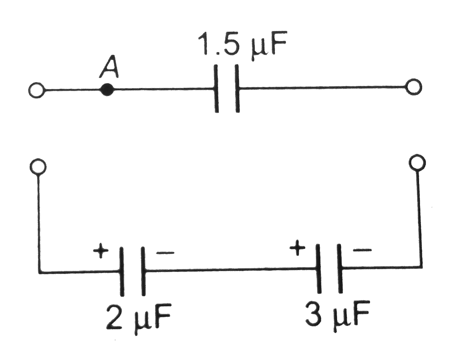
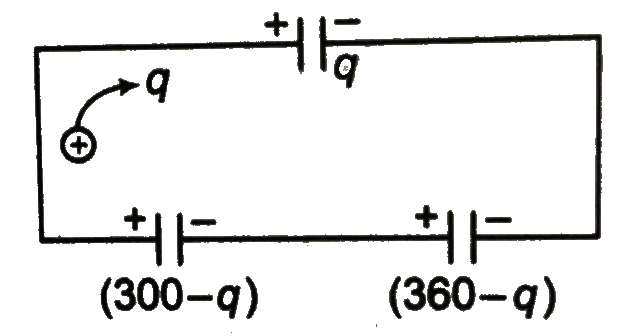
  3. Two capacitors of 2muF and 3muF are charged to 150 V and 120 V, respec...

    Text Solution

    |

  4. A parallel plate capacitor is charged and then the battery is disconne...

    Text Solution

    |

  5. A capacitor of 2F (practically not possible to have a capacity of 2F) ...

    Text Solution

    |

  6. given that potential differene across 1muF capacitor is 10V. Then,

    Text Solution

    |

  7. The capacitor C1 in the figure shown initially carries a charge q0. Wh...

    Text Solution

    |

  8. The capacitor C1 in the flgure shown initially carries a charge q0. Wh...

    Text Solution

    |

  9. Figure shows a parallel plate capacitor with plate area A and plate se...

    Text Solution

    |

  10. Figue shows a parallel plate capacitor with plate area A and plate sep...

    Text Solution

    |

  11. Five identical conducting plates, 1, 2,3,4 and 5 are fixed parallel pl...

    Text Solution

    |

  12. A 8uF capacitor C1 is charged to V0 = 120 V. The charging battery is t...

    Text Solution

    |

  13. Condensers with capacities C, 2 C, 3C and 4C are charged to the voltag...

    Text Solution

    |

  14. In the circuit shown, a time varying voltage V = 2000t volt is applied...

    Text Solution

    |

  15. A capacitor of capacitance 5muF is connected to a source of constant e...

    Text Solution

    |

  16. Analyse the given circuit in the steady state condition. Charge on the...

    Text Solution

    |

  17. Find the potential difference between points M and N of the system sho...

    Text Solution

    |

  18. In the given circuit diagram, find the charges which flow through dire...

    Text Solution

    |

  19. Two capacitors A and B with capacities 3muF and 2muF are charged to a ...

    Text Solution

    |

  20. The capactor C1 in the figure initially carries a charge q0. When the ...

    Text Solution

    |