Home
Class 12
PHYSICS
In a series C-R circuit shown in figureu...

In a series `C-R` circuit shown in figureure, the applied voltage is `10 V` and the voltage across capacitor is found to`8 V`. The voltage across `R`, and the phase difference between current and the applied voltage will respectively be
.

A

`6V, tan^-1(4/3)`

B

`3V,tan^-1(3/4)`

C

`6V,tan^-1(3/4)`

D

none of these

Text Solution

Verified by Experts

The correct Answer is:
A

`V_R=sqrt(V^2-V_C^2)=sqrt((10)^2-(8)^2)=6V`
`tanphi=X_C/X_R=V_C/V_R=8/6=4/3`
Promotional Banner

Topper's Solved these Questions

  • ALTERNATING CURRENT

    DC PANDEY ENGLISH|Exercise Level- 2More Than One Correct|8 Videos
  • ALTERNATING CURRENT

    DC PANDEY ENGLISH|Exercise Level 2 Comprehension|6 Videos
  • ALTERNATING CURRENT

    DC PANDEY ENGLISH|Exercise Level - 1 Subjective|6 Videos
  • ATOMS

    DC PANDEY ENGLISH|Exercise MEDICAL ENTRANCES GALLERY|42 Videos

Similar Questions

Explore conceptually related problems

In the circuit shown in the figure, the total charge is 750 mu C and the voltage across capacitor C_2 is 20 V. Then the charge on capacitor C_2 is:

The phase difference between voltage and current in series L-C circuit is

In series LCR circuit, the phase difference between voltage across L and voltage across C is

In a series L-C circuit, the applied voltage is V_0. if omega is very low, then the voltage drop across the inductor V_L and capacitor V_C are .

In a series L-C-R circuit, currenrt in the circuit is 11A when the applied voltage is 220 V . voltage across the caspcitor is 200 V . If the value of resistor is 20 Omega , then the voltage across the unknown inductor is

An Ac voltage V=V_0 sin 100t is applied to the circuit, the phase difference between current and voltage is found to be pi/4 , then .

An Ac voltage V=V_0 sin 100t is applied to the circuit, the phase difference between current and voltage is found to be pi/4 , then .

In the LCR circuit shown in figure unknown resistance and alternating voltage source are connected.When swith S is closed then there is a phase difference of pi/4 between current and applied voltage and voltage across resister is 100/sqrt2 V .When switch is open current and applied voltage are in same phase.Neglecting resistance of connecting wire answer the following questions : Peak voltage of applied voltage sources is:

In a series LCR circuit resistance R = 10Omega and the impedance Z = 10 Omega The phase difference between the current and the voltage is

In the LCR circuit shown in figure unknown resistance and alternating voltage source are connected.When swith S is closed then there is a phase difference of pi/4 between current and applied voltage and voltage across resister is 100/sqrt2 V .When switch is open current and applied voltage are in same phase.Neglecting resistance of connecting wire answer the following questions : Resonance frequency of circuit is:

DC PANDEY ENGLISH-ALTERNATING CURRENT-Level- 2 Single Correct
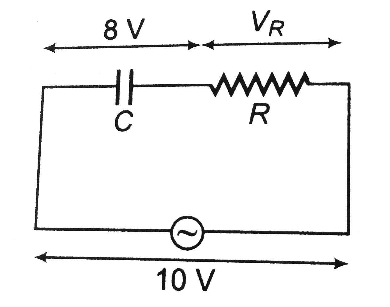
  1. A capacitor and resistor are connected with an AC source as shown in f...

    Text Solution

    |

  2. A circuit contains resistance R and an inductance L in series. An alte...

    Text Solution

    |

  3. In the circuit shown in figureure the AC source gives a voltage V=20co...

    Text Solution

    |

  4. A signal generator supplies a sine wave of 200V, 5kHz to the circuit s...

    Text Solution

    |

  5. A complex current wave is given by i=(5+5sin100omegat)A. Its average v...

    Text Solution

    |

  6. An Ac voltage V=V0 sin 100t is applied to the circuit, the phase diffe...

    Text Solution

    |

  7. In series L-C-R circuit, voltge drop across resistance is 8V, across i...

    Text Solution

    |

  8. Consider in L-C-R circuit as shown in figureure with an AC source of p...

    Text Solution

    |

  9. The adjoining figure shows an AC circuit with resistane R, inductance ...

    Text Solution

    |

  10. When an alternating voltage of 220 V is applied across a device P, a c...

    Text Solution

    |

  11. In a parallel L-C-R circuit as shown in figureure if IR,IL,IC and I re...

    Text Solution

    |

  12. In a series L-C-R circuit, currenrt in the circuit is 11A when the app...

    Text Solution

    |

  13. In the circuit shown in figure, the power consumed is .

    Text Solution

    |

  14. In a series L-C circuit, the applied voltage is V0. if omega is very l...

    Text Solution

    |

  15. A coil, a capacitor and an AC source of rms voltage 24 V are connected...

    Text Solution

    |

  16. In a series C-R circuit shown in figureure, the applied voltage is 10 ...

    Text Solution

    |

  17. An AC voltage source described by V=10cos(pi/2)t is connected to a 1mu...

    Text Solution

    |

  18. An AC voltage source V=V0sinomegat is connected across resistance R an...

    Text Solution

    |