Home
Class 11
PHYSICS
In figure , assuming the diodes to be id...

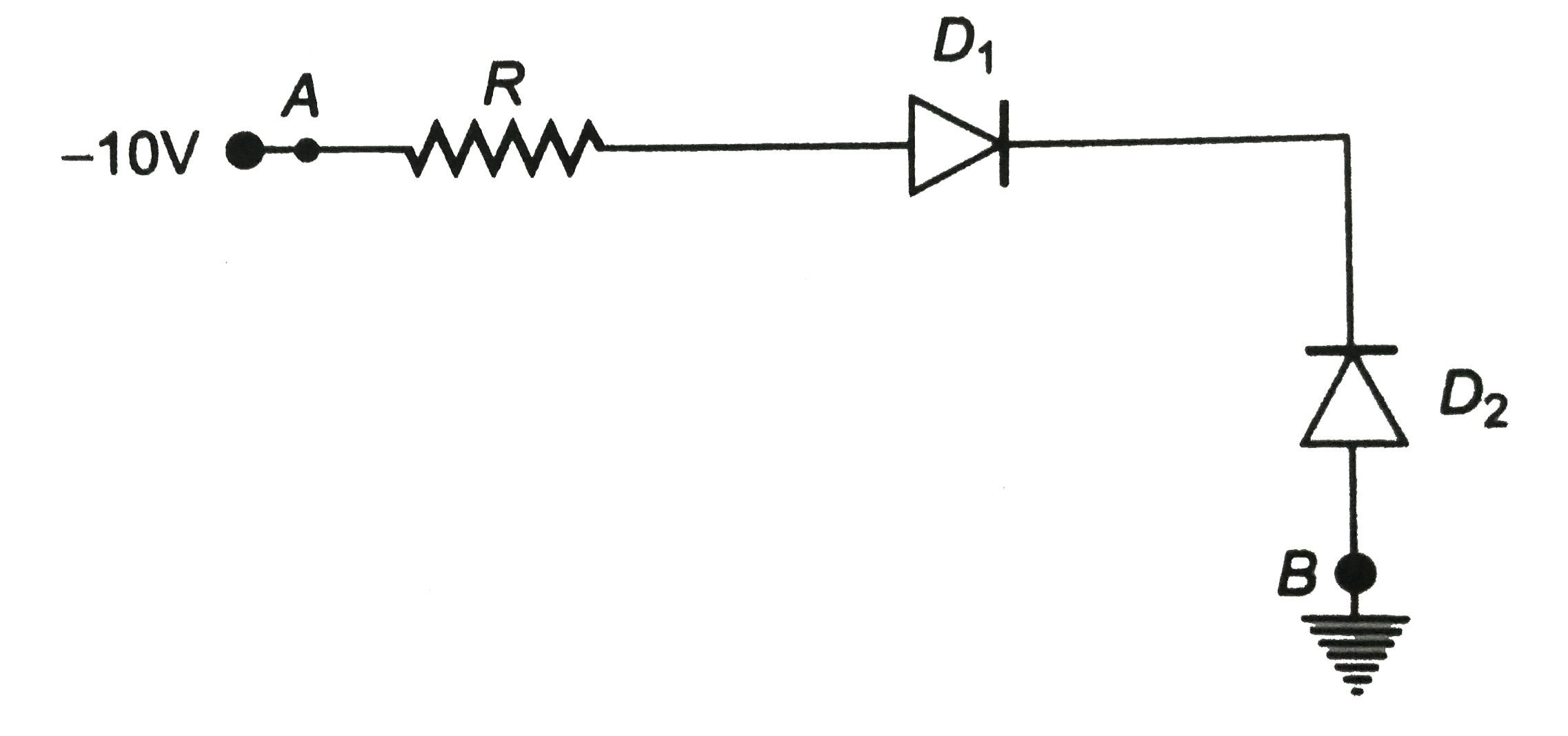
In figure , assuming the diodes to be ideal ,

A

`D_(1)` is forward biased, `D_(2)` is reverse biased and hence current flows from A to B

B

`D_(2)` is forward biased, `D_(1)` is reverse biased and hence no current flows from B to A and vice-versa

C

`D_(1)` and `D_(2)` are both forward biased and hence current flows from A to B

D

`D_(1)` and `D_(2)` are both reverse biased and hence no current flows from A to B and vice-versa

Text Solution

Verified by Experts

The correct Answer is:
B
Promotional Banner

Topper's Solved these Questions

  • SEMICONDUCTORS AND ELECTRONIC DEVICES

    DC PANDEY ENGLISH|Exercise More than One Option is Correct|3 Videos
  • ROTATIONAL MOTION

    DC PANDEY ENGLISH|Exercise Integer Type Questions|17 Videos
  • SIMPLE HARMONIC MOTION

    DC PANDEY ENGLISH|Exercise Integer type questions|14 Videos

Similar Questions

Explore conceptually related problems

Find the reading of ammeter A and voltmeter V shown in the figure assuming the instruments to be ideal

Two moles of Helium gas undergo a reversible cyclic process as shown in figure. Assuming gas to be ideal, what is the net work involved in the cyclic process ?

Two moles of Helium gas undergo a reversible cyclic process as shown in figure. Assuming gas to be ideal, what is the net work involved in the cyclic process ?

Two moles of Helium gas undergo a reversible cyclic process as shown in figure. Assuming gas to be ideal, what is the net work involved in the cyclic process ?

A diode is a device that allows current to be carried in only one direction (the direction indicated by the arrowhead in its circuit symbol). Find (approximately) in terms of DeltaV and R the average power delivered to the diode circuit of the figure. Assume that the diodes are ideal and DeltaV is the rms voltage applied to the circuit.

In the circuit shown, the average power dissipated in the resistor is (assume diode to be ideal)

An ideal diode is connected in a circuit with resistance R=5Omega and V=10 volt as shown in figure maximum and minimum value of output voltage. When no load applied is (assume diode to be ideal)

In the following figure all surfaces are assumed to be frictionless and pulley us assumed to be ideal. The block 'A' is projected towards the pulley 'P' with an intial velocity u_(0) then select correct option :

A fullwave P.N diode rectifier used load resistor of 1500 Omega . No filter is used. Assume each diode to have idealized characteristic with R_(f) = 10 Omega and R_(r) = ac . Since wave voltage applied to each diode has amplitude of 30 volts and frequency 50 Hz. Calculate. (i) Peak, d.c rms load current (ii) d.c power output (iii) A.C power input (iv) Rectifier efficiency.

In the circuit shown in figure, if the diode forward voltage drop is 0.3 V, then the voltage difference between A to B is,