A
B
C
D
Text Solution
Verified by Experts
The correct Answer is:


Similar Questions
Explore conceptually related problems
Recommended Questions
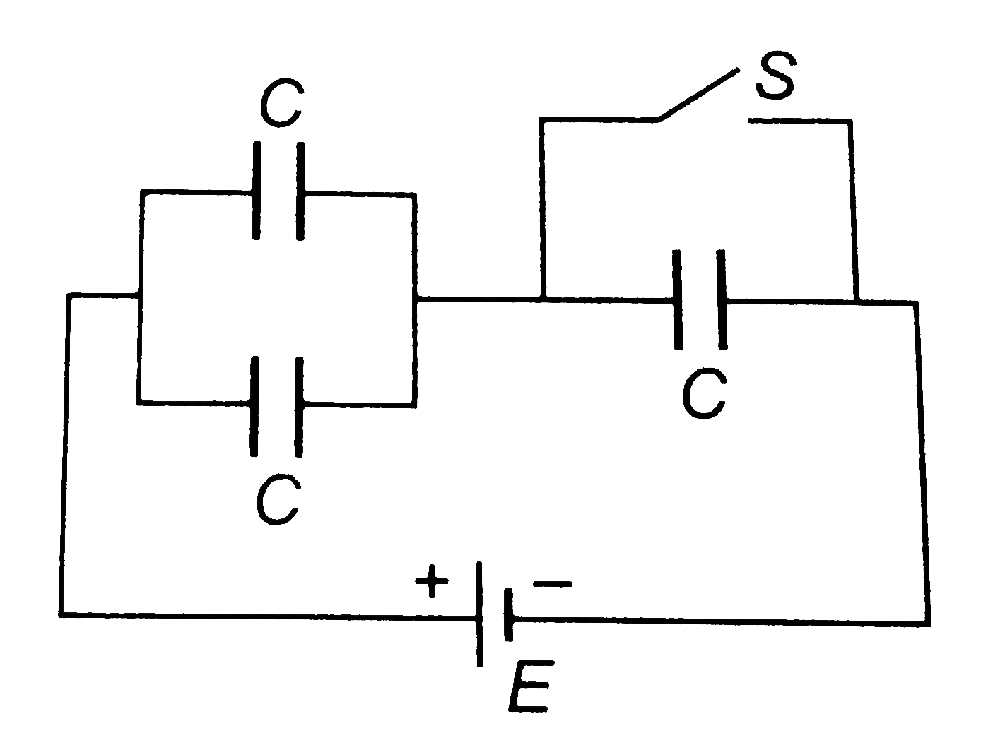
- In the circuit shown each capacitor has a capcitance C. The emf of the...
Text Solution
|
- In the circuit shown in fig. when the switch is closed, the capacitor ...
Text Solution
|
- In the LR circuit the switch S was closed for a long time. The ideal c...
Text Solution
|
- Four capacitors of capacitance C , 2C , 3C & 4C respectively are conne...
Text Solution
|
- The circuit shown consists of a switch (S), a battery (B) of emf E, a ...
Text Solution
|
- In the circuit shown, each capacitor has a capacitance C, The cell vol...
Text Solution
|
- In the circuit shown in figure, each capacitor has a capacitance C and...
Text Solution
|
- In the circuit shown above, when then switch S is closed,
Text Solution
|
- In the circuit shown in the figure, the capacitor C is charged to a po...
Text Solution
|