Home
Class 11
PHYSICS
Which of the following wiring diagrams c...

Which of the following wiring diagrams could be used to experimentally determine `R` using ohm's law? Assume an ideal voltmeter and an ideal ammeter.

A

B

C

D

Text Solution

AI Generated Solution

The correct Answer is:
To determine the resistance \( R \) using Ohm's law experimentally, we need to set up a circuit that allows us to measure both the current flowing through the resistor and the voltage across it. Here’s a step-by-step solution: ### Step 1: Understand Ohm's Law Ohm's law states that \( V = I \cdot R \), where: - \( V \) is the voltage across the resistor, - \( I \) is the current flowing through the resistor, - \( R \) is the resistance. To determine \( R \), we need to measure \( V \) and \( I \). ### Step 2: Set Up the Circuit 1. **Connect the Resistor**: Place the resistor \( R \) in the circuit. 2. **Connect the Ammeter**: Connect an ideal ammeter in series with the resistor. This allows us to measure the current \( I \) flowing through the resistor. 3. **Connect the Voltmeter**: Connect an ideal voltmeter in parallel with the resistor. This allows us to measure the voltage \( V \) across the resistor. ### Step 3: Measure Voltage and Current - Turn on the power supply and adjust it to a known value. - Record the current \( I \) displayed on the ammeter. - Record the voltage \( V \) displayed on the voltmeter. ### Step 4: Calculate Resistance Using the values obtained from the measurements: \[ R = \frac{V}{I} \] This formula gives us the resistance \( R \) of the resistor based on the measured voltage and current. ### Step 5: Repeat Measurements To ensure accuracy, repeat the measurements for different voltage settings and calculate \( R \) each time. The average value can provide a more reliable result. ### Conclusion The wiring diagram that connects the voltmeter in parallel and the ammeter in series with the resistor is the correct setup to experimentally determine \( R \) using Ohm's law. ---
Promotional Banner

Topper's Solved these Questions

  • COMMUNICATION SYSTEM

    DC PANDEY ENGLISH|Exercise Only One Option is Correct|27 Videos
  • ELASTICITY

    DC PANDEY ENGLISH|Exercise Medical entrances s gallery|21 Videos

Similar Questions

Explore conceptually related problems

Which of the following can be used to determine the charge on the sol?

In the following circuit, determine the reading of ideal voltmeter (V) and ideal ammeter (A).

Express which of the following set ups can be used to verify ohm's law?

Which of the following diagrams (figure) depicts ideal gas behaviour?

Which of the following dienes an dienophiles could be used to synthesise the following compound (A) ?

Which of the following techniques cannot be used to determine the genetic defect of an embryo?

Which of the following is used to determine the rate of transpiration in plants

Which of the following circuits gives the correct value of resistance, when computed by using R = (V//I) where V and I are voltmeter and ammeter reading, respectively? The meters are not ideal.

Which of the following options are CORRECT (ammeters are ideal).

Which of the following apparatus is used to determine the Young's modulus of the material of a gives given wires?

DC PANDEY ENGLISH-CURRENT ELECTRICITY-All Questions
  1. The equivalent resistance between the points A and B is:

    Text Solution

    |

  2. In the circuit shown, what is the potential different V(PQ) ?

    Text Solution

    |

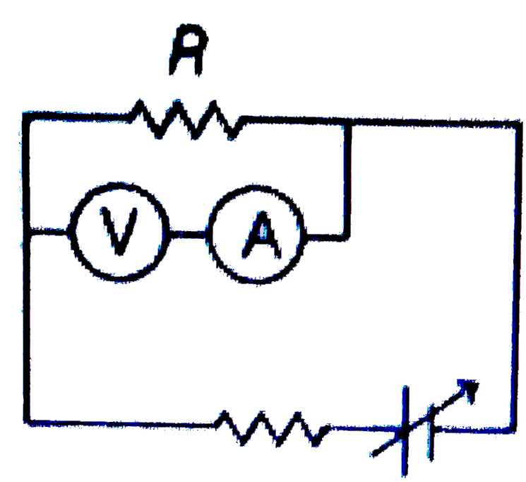
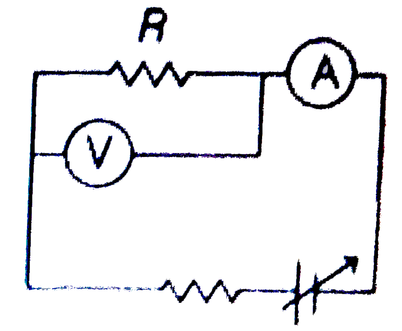
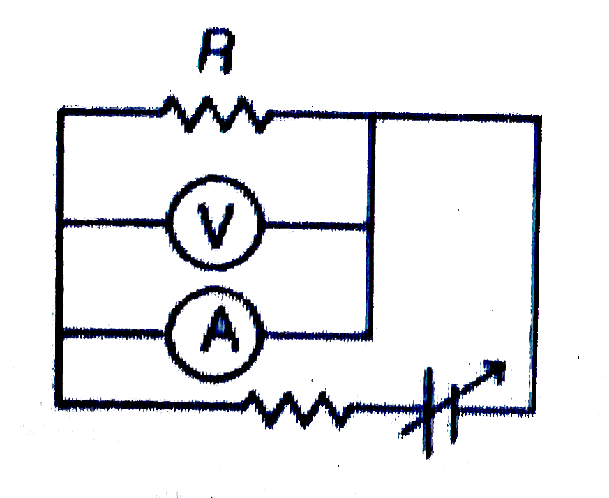
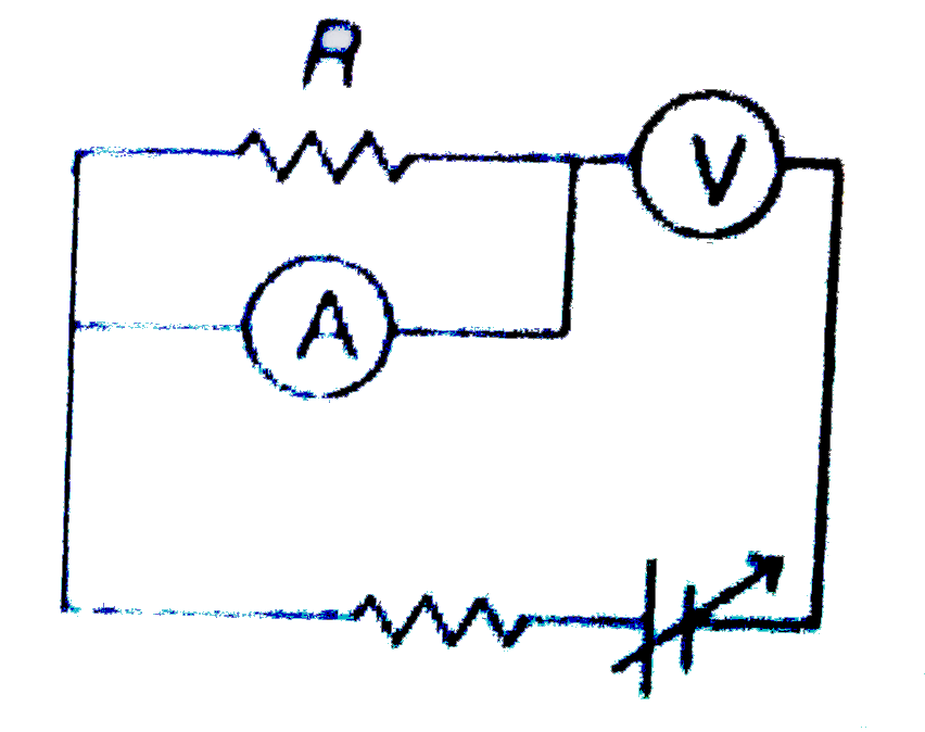
  3. Which of the following wiring diagrams could be used to experimentally...

    Text Solution

    |

  4. In the given circuit current flowing through the resistance 20Omega is...

    Text Solution

    |

  5. Power generated across a uniform wire connected across a supply is H. ...

    Text Solution

    |

  6. Rate of dissipation of Joule's heat in resistance per unit volume is (...

    Text Solution

    |

  7. The variation of current (I) and voltage (V) is as shown in figure A. ...

    Text Solution

    |

  8. Six resistors each of 10 ohm are connected shown. The equivalent resis...

    Text Solution

    |

  9. Thirteen resistances each of resistance R ohm are connected in the cir...

    Text Solution

    |

  10. In the given network, the euqivalent resistance between A and B is

    Text Solution

    |

  11. The equivalent resistance between points A and B

    Text Solution

    |

  12. A conductor with rectangular cross section has dimensions (axx2axx4a) ...

    Text Solution

    |

  13. Which of the following has the maximum resistance?

    Text Solution

    |

  14. The length of a potentiometer wire is l. A cell of emf E is balanced a...

    Text Solution

    |

  15. A cell develops the same power across two resistances R(1) and R(2) se...

    Text Solution

    |

  16. Two wires of same dimension but resistivity p(1) and p(2) are connecte...

    Text Solution

    |

  17. Current passing through 3 Omega resistance is

    Text Solution

    |

  18. Current passing through 1 Omega resistance is zero. Then the emf E is

    Text Solution

    |

  19. As the switch S is closed in the circuit shown in figure, current pass...

    Text Solution

    |

  20. In the circuit shown in figure

    Text Solution

    |