Home
Class 11
PHYSICS
In the circuit shown in figure switch S ...

In the circuit shown in figure switch S can be shift to position A or position B. Current though resistance is say `i_(1)` when switch is in position. A and when switch is in position B, then

A

`i_(1) = 2.5 A`

B

`i_(2) = 0`

C

both (a) and (b) are correct

D

both (a) and (b) wrong

Text Solution

Verified by Experts

The correct Answer is:
A
Promotional Banner

Topper's Solved these Questions

  • COMMUNICATION SYSTEM

    DC PANDEY ENGLISH|Exercise Only One Option is Correct|27 Videos
  • ELASTICITY

    DC PANDEY ENGLISH|Exercise Medical entrances s gallery|21 Videos

Similar Questions

Explore conceptually related problems

In the given circuit diagram figure, switch S_w is shifted from position 1 to position 2. Then

In the circuit as shown in the figure, switch S is added at t=0. Then:

Condsider . In the circuit shown is the switch can be shifted to positions 1 and 2 The charge on capacitor C_(1) when the switch is at position 1 is.

In the circuit shown in figure switch S is closed at time t=0 At what time current through 3Omega resistance and 1H inductor are equal?

In the circuit shown in figure switch S is thrown to position 1 at t=0 . when the current in the resistort is 1A , it is shifted to position 2. the total heat generated in the circuit after shifting to position 2 is

In the circuit shown in figure the switch S is closed at t = 0. A long time after closing the switch

In the circuit shown in figure switch S is closed at time t=0 Current I from the battery at time t is given by

In the circuit shown, the switch S is shifted to position 2 from position 1 at t=0 , having been in position 1 for a long time.Find the current in the circuit as a function of time.

In the circuit shown, the switch S is shifted to position 2 from position 1 at t=0 , having been in position 1 for a long time.Find the current in the circuit as a function of time.

In the circuit shows in Fig switch S is shifed to position 2 from position 1 at t = 0 , having been on position 1 for a long time. The current in the circuit just after shifting of switch will be (battery and both the inductors are ideal)

DC PANDEY ENGLISH-CURRENT ELECTRICITY-All Questions
  1. The equivalent resistance between points A and B is

    Text Solution

    |

  2. A battery of internal resistance 4 Omega is connected to he network of...

    Text Solution

    |

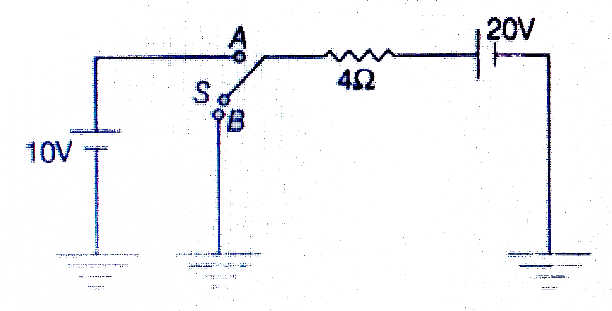
  3. In the circuit shown in figure switch S can be shift to position A or ...

    Text Solution

    |

  4. A galvanometer has resistance G and full scale deflection current i. T...

    Text Solution

    |

  5. Four resistance are connected to a DC battery as shown in figure. Maxi...

    Text Solution

    |

  6. A hollow cylinder of specific resistance rho, inner radius R, outer ra...

    Text Solution

    |

  7. A group of identical cells (all in parallel) are connected to an exter...

    Text Solution

    |

  8. Five identical cells are connected in parallel. Now, polarity of one o...

    Text Solution

    |

  9. In the circuir shown in figure, current is zero through

    Text Solution

    |

  10. If internal resistance of a cell is proportional to current drawn from...

    Text Solution

    |

  11. A galvanometer, together with an unknown resistance in series, is conn...

    Text Solution

    |

  12. In the figur shown, the thermal power generated in 'Y' is maximum when...

    Text Solution

    |

  13. A cell of emf E having an internal resistance R varies with R as shown...

    Text Solution

    |

  14. Six wires each of resistance r form a tetrahedron. The equivalent resi...

    Text Solution

    |

  15. A series parallel combination battery consisting of a large number N ...

    Text Solution

    |

  16. One end of a Nichrome wire of length 2L and cross-sectional area A is ...

    Text Solution

    |

  17. In the circuit shown, the resistance are given ohms and the battery is...

    Text Solution

    |

  18. In the diagram, resistance between any two junction is R. Equivalent r...

    Text Solution

    |

  19. A battery of emf E(0) = 12 V is connected across a 4 m long uniform wi...

    Text Solution

    |

  20. In the circuit shown, what is the potential difference V(PQ)?

    Text Solution

    |