A
B
C
D
Text Solution
Verified by Experts
The correct Answer is:


Topper's Solved these Questions
Similar Questions
Explore conceptually related problems
DC PANDEY ENGLISH-CURRENT ELECTRICITY-All Questions
- In series, potential difference distributes in direct ratio of resista...
Text Solution
|
- In series, potential difference distributes in direct ratio of resista...
Text Solution
|
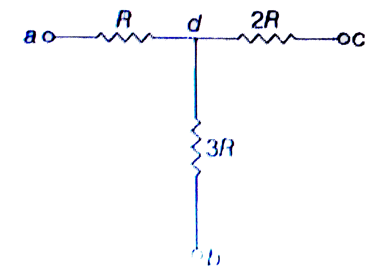
- In the circuit shown in figure points a, b and c are maintained at con...
Text Solution
|
- In the circuit shown in figure points a, b and c are maintained at con...
Text Solution
|
- All bulbs consume same power. The resistance of bulb 1 is 36 Omega . ...
Text Solution
|
- All bulbs consume same power. The resistance of bulb 1 is 36 Omega . ...
Text Solution
|
- All bulbs consume same power. The resistance of bulb 1 is 36 Omega . ...
Text Solution
|
- The power dissipated in resistor R(3) shown in the figure is 15 W. The...
Text Solution
|
- The power dissipated in resistor R(3) shown in the figure is 15 W. The...
Text Solution
|
- The power dissipated in resistor R(3) shown in the figure is 15 W. The...
Text Solution
|
- Match the following
Text Solution
|
- Three wires of same material are connected in parallel to a source of ...
Text Solution
|
- In the figure shown, each resistance is R. Match the following
Text Solution
|
- Six batteris of increasing emf and increasing internal resistance are ...
Text Solution
|
- In the potentiometer arrangement shown in figure null point is obtaine...
Text Solution
|
- In the circuit shown in figure, if a resistance R connected in parall...
Text Solution
|
- In the circuit shown in figure, match following.
Text Solution
|
- Current is flowing through a wire of non-uniform cross section. Cross ...
Text Solution
|
- In the circuit shown in figure , R(1)=R(2)=R(3)=R. Match the following
Text Solution
|
- In the circuit shown in figure, match the match the following
Text Solution
|