A
B
C
D
Text Solution
Verified by Experts
The correct Answer is:


Topper's Solved these Questions
ELECTROSTATIC POTENTIAL AND CAPACITORS
DC PANDEY ENGLISH|Exercise (B) Chapter exercises|17 VideosELECTROSTATIC POTENTIAL AND CAPACITORS
DC PANDEY ENGLISH|Exercise (C) Chapter exercises|50 VideosELECTROSTATIC POTENTIAL AND CAPACITORS
DC PANDEY ENGLISH|Exercise Check point 2.5|20 VideosELECTROMAGNETIC WAVES
DC PANDEY ENGLISH|Exercise Sec C|22 VideosELECTROSTATICS
DC PANDEY ENGLISH|Exercise Medical entrances gallery|37 Videos
Similar Questions
Explore conceptually related problems
DC PANDEY ENGLISH-ELECTROSTATIC POTENTIAL AND CAPACITORS-(A) Chapter exercises
- An electron initially at rest falls a distance of 1.5 cm in a uniform ...
Text Solution
|
- A long, hollow conducting cylinder is kept coaxially inside another lo...
Text Solution
|
- The potential at a point x ( measured in mu m) due to some charges sit...
Text Solution
|
- Three charges Q, +q and +q are placed at the vertices of a right-angle...
Text Solution
|
- Four point charges each +q is placed on the circumference of a circle ...
Text Solution
|
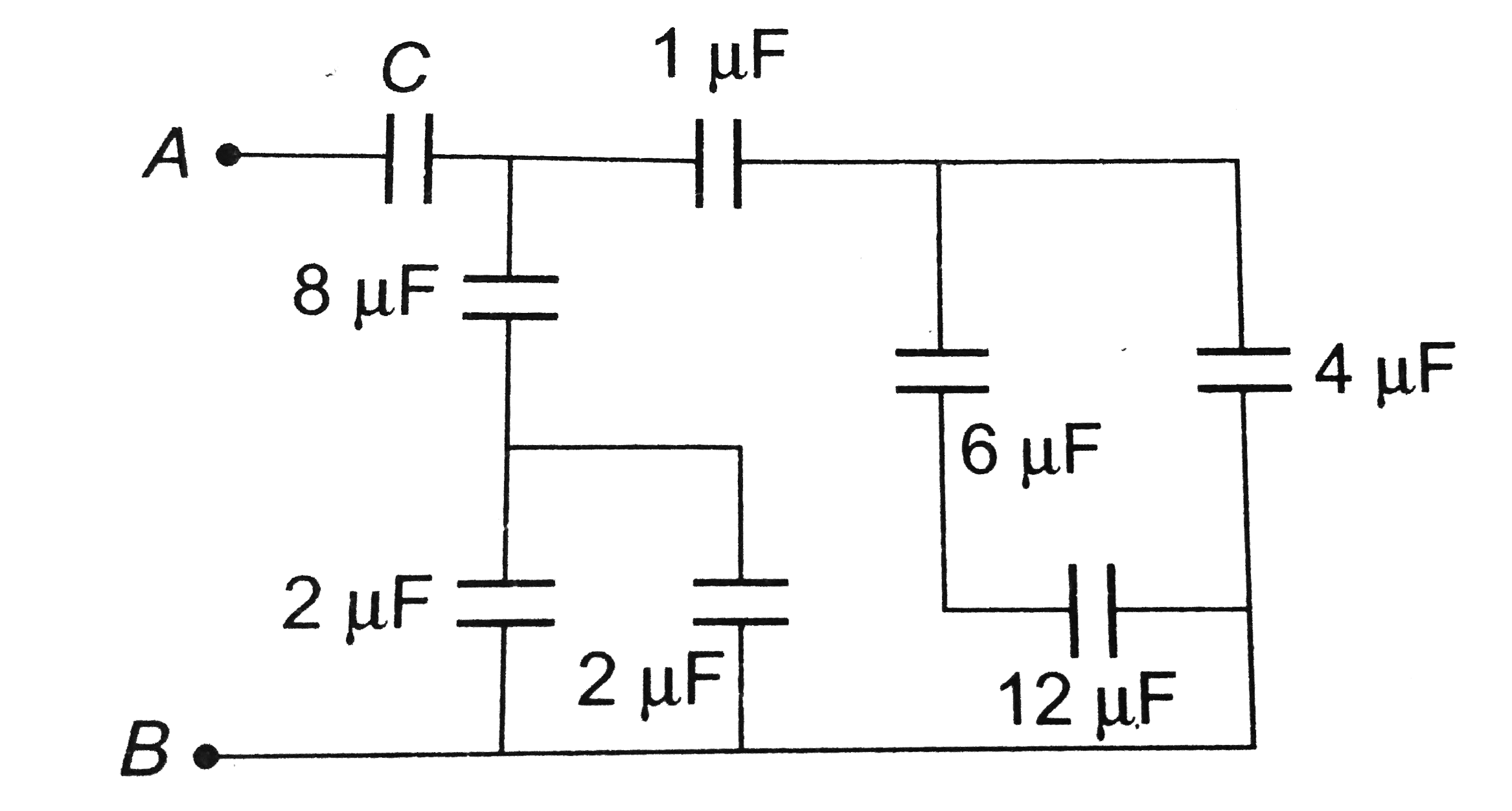
- The resultant capacitance between A and B in the following figure is e...
Text Solution
|
- In the following circuit, the resultant capacitance between A and B is...
Text Solution
|
- A small conducting sphere of radius r is lying concentrically inside a...
Text Solution
|
- A parallel plate air capacitor has a capacitance C. When it is half fi...
Text Solution
|
- Charge Q is uniformly distributed on a dielectric rod AB of length 2l....
Text Solution
|
- The arc AB with the centre C and the infinitely long wire having line...
Text Solution
|
- Two charges q(1) and q(2) are placed 30 cm apart, as shown in the figu...
Text Solution
|
- Three identical metallic uncharged spheres A, B and C of radius a are ...
Text Solution
|
- The curve represents the distribution of potential along the staight l...
Text Solution
|
- Seven capacitors, each of capacitance 2 muF, are to be combined to obt...
Text Solution
|
- A solid conducting sphere of radius a having a charge q is surrounde...
Text Solution
|
- Three identical charges are placed at corners of a equilateral triange...
Text Solution
|
- Two capacitors C(1) and C(2) = 2C(1) are connected in a circuit with a...
Text Solution
|
- Five identical plates each of area a are joined as shown in the figure...
Text Solution
|
- In the figure shown, what is the potential difference between the poin...
Text Solution
|