Home
Class 12
PHYSICS
In the circuit diagram,heat produces in ...

In the circuit diagram,heat produces in R, 2R and `1.5 R` are in the ratio of

A

`4:2:3`

B

`8:4:27`

C

`2:4:3`

D

`27:8:4`

Text Solution

Verified by Experts

The correct Answer is:
B
Promotional Banner

Topper's Solved these Questions

  • CURRENT ELECTRICITY

    DC PANDEY ENGLISH|Exercise Match the columns|4 Videos
  • COMMUNICATION SYSTEM

    DC PANDEY ENGLISH|Exercise Subjective|11 Videos
  • ELECTROMAGNETIC INDUCTION

    DC PANDEY ENGLISH|Exercise Medical entrances gallery|25 Videos

Similar Questions

Explore conceptually related problems

The circuit is shown in the following figure. The potential at points A, B, C, D and O are given. The currents in the resistance R_(1), R_(2) and R_(3) are in the ratio of 4:2:1 . What is the ratio of resistance R_(1),R_(2),R_(3) and R_(4) ?

Two resistances R and 2R are connected in parallel in an electric circuit. The thermal energy developed in R and 2R are in the ratio

two resistors R and 2R are connected in series in an electric circuit. The thermal energy developed in R and 2R are in the ratio

Two resistors R and 2R are connected in series in an electric circuit. The thermal energy developed in R and 2R are in the ratio

In the situation shown, resistance R_(1),R_(2) and R_(3) are in the ratio 3:2:1 , then

Three resistors R_1, R_2 and R_3 are to be combined to form an electrical circuit as shown in the figure. It is found that when R_1 R_2 and R_3 are put respectively in positions A, B and C, the effective resistance of the circuit is 70 Omega When R_2, R_3 and R_1 are put respectively in position A, B and C the effective resistance is 35 Omega and when R_3, R_1 and R_2 are respectively put in the position A, B and C, the effective resistance is 42 Omega The resistance R_(1): R_(2): R_(3 ) are in the ratio

In the circuit diagram given below, three resistors R_(1),R_(2) , and R_(3) of 5 Omega, 10 Omega and 30 Omega , respectively are connected as shown. Calculate: (a) current through each resistor. (b) total current in the circuit. (c) total resistance in the circuit.

Three resistors R_1, R_2 and R_3 are to be combined to form an electrical circuit as shown in the figure. It is found that when R_1 R_2 and R_3 are put respectively in positions A, B and C, the effective resistance of the circuit is 70 Omega When R_2, R_3 and R_1 are put respectively in position A, B and C the effective resistance is 35 Omega and when R_3, R_1 and R_2 are respectively put in the position A, B and C, the effective resistance is 42 Omega If R_(1), R_(2) and R_(3) are put in series, the effective resistance will be

Three resistors R_1, R_2 and R_3 are to be combined to form an electrical circuit as shown in the figure. It is found that when R_1 R_2 and R_3 are put respectively in positions A, B and C, the effective resistance of the circuit is 70 Omega When R_2, R_3 and R_1 are put respectively in position A, B and C the effective resistance is 35 Omega and when R_3, R_1 and R_2 are respectively put in the position A, B and C, the effective resistance is 42 Omega If R_(1), R_(2 )and R_(3) are all connected in parallel, the effective resistance will be

The galvanometer, in each of the two given circuits deos not show any deflection. Find the ratio of the resistors R_(1) and R_(2) used in these two circuits.

DC PANDEY ENGLISH-CURRENT ELECTRICITY-Medical entrances gallery
  1. Three conductors draw respectively currents of 1 A, 2 A and 4 A when c...

    Text Solution

    |

  2. The massses of the three wires of copper are in the ratio 1 : 3 : 5. A...

    Text Solution

    |

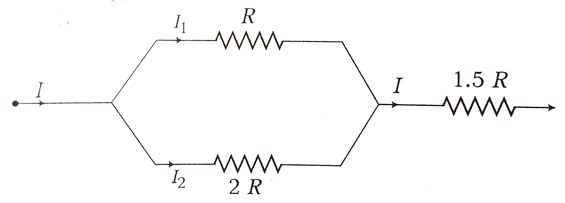
  3. In the circuit diagram,heat produces in R, 2R and 1.5 R are in the ra...

    Text Solution

    |

  4. Which one of the following electrical meter has the smallest resistanc...

    Text Solution

    |

  5. Two wires of the same materical having equal area of cross-section hav...

    Text Solution

    |

  6. Two bulbs 60 W and 100 W designed for voltage 220 V are connected in s...

    Text Solution

    |

  7. The drift speed of electrons in copper wire of diameter and length l i...

    Text Solution

    |

  8. A potentiometer wire of length 10 m and resistance 10 Omega per meter ...

    Text Solution

    |

  9. If a wire is stretched to four times its length, then the specific res...

    Text Solution

    |

  10. For the circuit shown in figure given below, the equivalent resistance...

    Text Solution

    |

  11. Two resistors of 6 Omega " and " 9 Omega are connected in series to a ...

    Text Solution

    |

  12. A current of 2 A flows in a system of conductor as shown. The potentia...

    Text Solution

    |

  13. A cell sends a current through a resistance R(1) for time t, next the...

    Text Solution

    |

  14. When a current of (2.5 +- 0.5) ampere flows through a wire, it develop...

    Text Solution

    |

  15. To draw the maximum current from a combination of cells, how should be...

    Text Solution

    |

  16. The variation between V-I has shown by graph for heating filament

    Text Solution

    |

  17. Two bulbs when connected in parallel to a source take 60 W each, the p...

    Text Solution

    |

  18. The equivalent resistance resistance between A and B of network shown ...

    Text Solution

    |

  19. A galvanometer having resistance of 50 Omega requires a current of 100...

    Text Solution

    |

  20. Two cells when connected in series are balanced on 8 m on a potentiome...

    Text Solution

    |