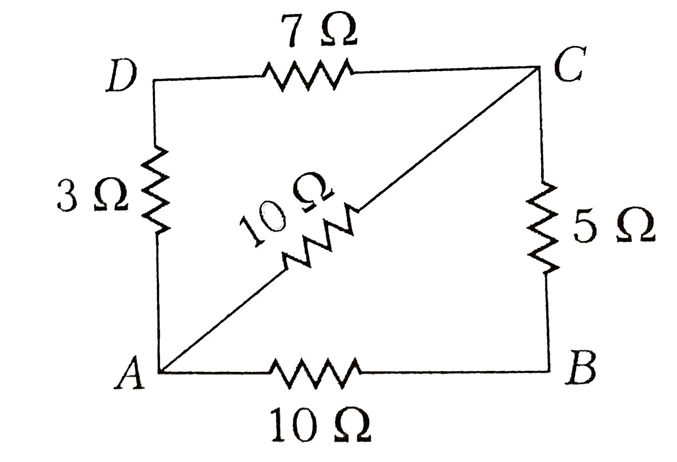
A
B
C
D
Text Solution
Verified by Experts
The correct Answer is:


Topper's Solved these Questions
Similar Questions
Explore conceptually related problems
DC PANDEY ENGLISH-CURRENT ELECTRICITY-Medical entrances gallery
- A potentiometer wire of length 10 m and resistance 10 Omega per meter ...
Text Solution
|
- If a wire is stretched to four times its length, then the specific res...
Text Solution
|
- For the circuit shown in figure given below, the equivalent resistance...
Text Solution
|
- Two resistors of 6 Omega " and " 9 Omega are connected in series to a ...
Text Solution
|
- A current of 2 A flows in a system of conductor as shown. The potentia...
Text Solution
|
- A cell sends a current through a resistance R(1) for time t, next the...
Text Solution
|
- When a current of (2.5 +- 0.5) ampere flows through a wire, it develop...
Text Solution
|
- To draw the maximum current from a combination of cells, how should be...
Text Solution
|
- The variation between V-I has shown by graph for heating filament
Text Solution
|
- Two bulbs when connected in parallel to a source take 60 W each, the p...
Text Solution
|
- The equivalent resistance resistance between A and B of network shown ...
Text Solution
|
- A galvanometer having resistance of 50 Omega requires a current of 100...
Text Solution
|
- Two cells when connected in series are balanced on 8 m on a potentiome...
Text Solution
|
- In the given circuit diagram if each resistance is of 10 Omega, then t...
Text Solution
|
- When the current i is flowing through a conductor, the drift velocity ...
Text Solution
|
- A wire has a resistance of 12 ohm . It is bent in the form of equilat...
Text Solution
|
- In the circuit shown the cells A and B have negligible resistance. For...
Text Solution
|
- A milli voltmeter of 25 milli volt range is to be converted into an am...
Text Solution
|
- If voltage across a bulb rated 220 volt-100 watt drops by 2.5 % of its...
Text Solution
|
- 6Omega and 12Omega resistors are connected in parallel. This combinati...
Text Solution
|