Home
Class 12
PHYSICS
Which of the following plots may represe...

Which of the following plots may represent is impedence of a series LCR combination?

A

B

C

D

Text Solution

AI Generated Solution

The correct Answer is:
To determine which plot represents the impedance of a series LCR (Inductor-Capacitor-Resistor) combination, we can follow these steps: ### Step-by-Step Solution: 1. **Understand the Impedance Formula**: The impedance \( Z \) of a series LCR circuit is given by the formula: \[ Z = \sqrt{R^2 + (X_L - X_C)^2} \] where \( X_L = \omega L \) (inductive reactance) and \( X_C = \frac{1}{\omega C} \) (capacitive reactance). 2. **Identify the Conditions**: - **Condition 1**: When \( X_L = X_C \) (resonance condition), then \( Z = R \). - **Condition 2**: When \( X_L > X_C \) (inductive dominance), \( Z \) increases as frequency increases. - **Condition 3**: When \( X_C > X_L \) (capacitive dominance), \( Z \) also increases but starts from a lower value. 3. **Plot the Impedance**: - On the x-axis, we plot frequency \( \omega \). - On the y-axis, we plot impedance \( Z \). - The graph will show: - A minimum point at resonance (\( Z = R \)). - An increase in impedance as we move away from resonance in both directions (either \( X_L \) or \( X_C \) dominating). 4. **Analyze the Options**: - Check each option to see which one reflects the behavior described: - A curve that dips to a minimum at the resonance frequency and rises on either side indicates the correct representation of impedance in a series LCR circuit. 5. **Conclusion**: - After analyzing the provided options, the correct plot that represents the impedance of a series LCR combination is identified. ### Final Answer: The correct option is **Option C**.
Promotional Banner

Topper's Solved these Questions

  • ALTERNATING CURRENT

    DC PANDEY ENGLISH|Exercise Level 2 Subjective|10 Videos
  • ATOMS

    DC PANDEY ENGLISH|Exercise MEDICAL ENTRANCES GALLERY|42 Videos

Similar Questions

Explore conceptually related problems

Which of the following plots may represent the reactance of a series LC combination?

Which of the following plots may represent the reactance of a series LC combination? (##HCV_VOL2_C39_E01_020_Q01##)

Which of the shown graphs may represent the reactance of a series L-C combination?

The Y axis of the following graph may represent

Which of the following plots represents an ideal binary mixture?

Which of the following plots does not represent Boyle's law?

Which of the following may represent the curve x = 2y+ 3?

Which of the following may represent the direction of vecV_(AB) ?

Which of the following plots represents the behavior of an ideal binary liquid solution ?

Which of the following is the only correct combination for Lyman series ?

DC PANDEY ENGLISH-ALTERNATING CURRENT-JEE MAIN
  1. An inductor coil stores U energy when i current is passed through it a...

    Text Solution

    |

  2. The dimensions of magnetic flux are

    Text Solution

    |

  3. Two inductors L(1) and L(2) are connected in parallel and a time varyi...

    Text Solution

    |

  4. A resistance is connected to a n AC source. If a capacitor is induced...

    Text Solution

    |

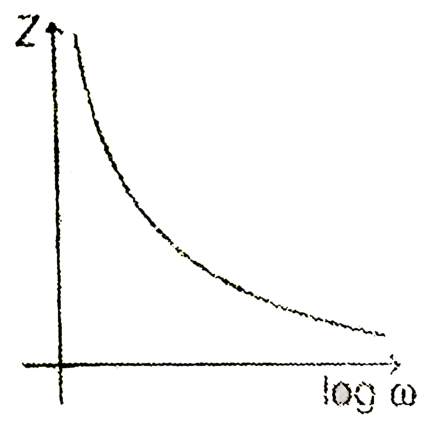
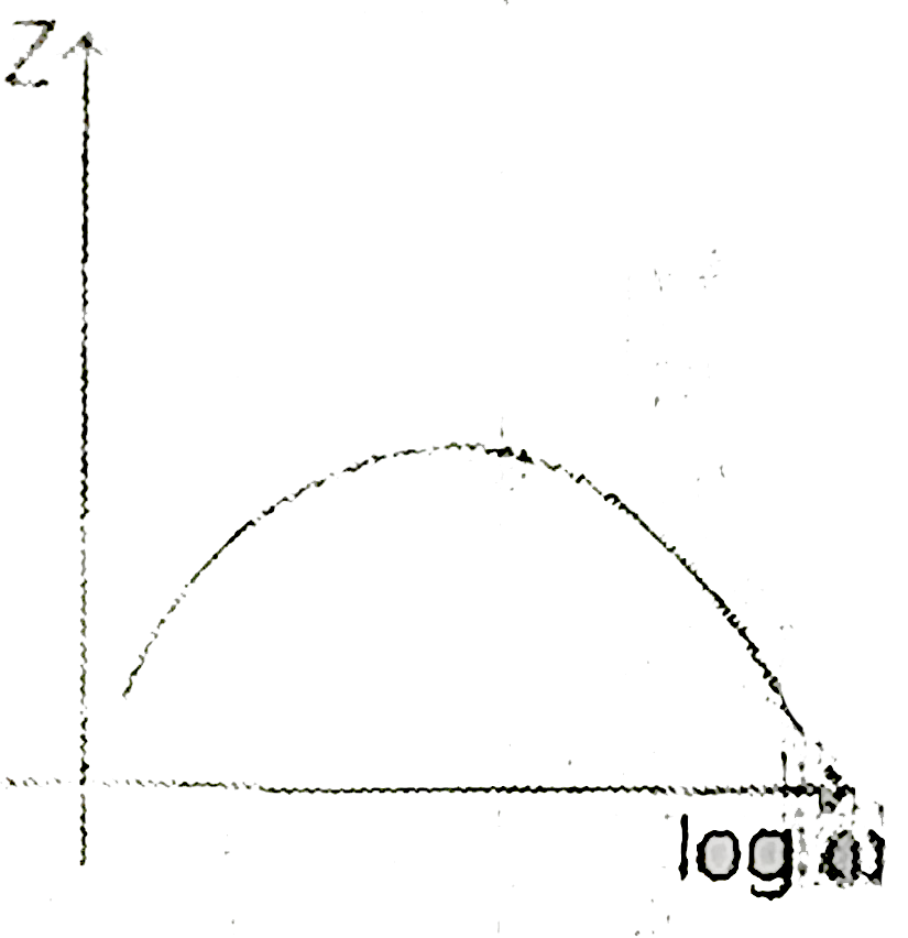
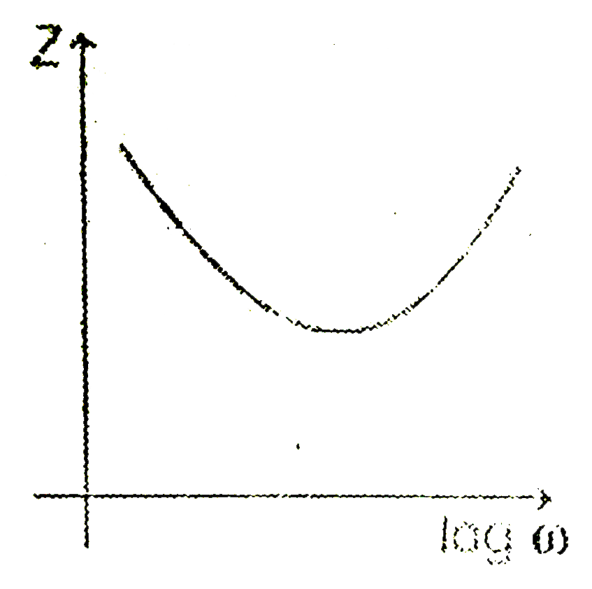
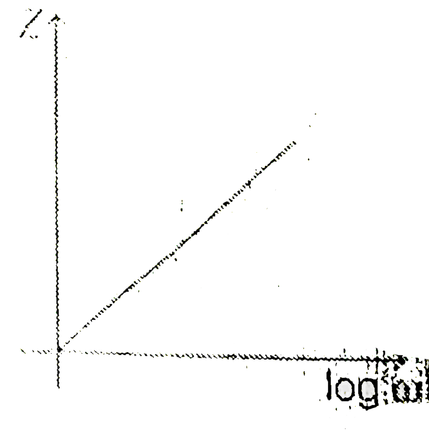
  5. Which of the following plots may represent is impedence of a series LC...

    Text Solution

    |

  6. An inductor-coil having some resistance is connected to an AC source. ...

    Text Solution

    |

  7. The variation of induced emf (E) with time (t) in a coil if a short ba...

    Text Solution

    |

  8. An inductor L is allowed to discharge through capacitor C. The emf ind...

    Text Solution

    |

  9. The voltage time (V-t) graoh for triangular wave having peak value (V0...

    Text Solution

    |

  10. A rectangular loop os sides of length l and b is placed in x-y plane. ...

    Text Solution

    |

  11. In an LCR circuit R=100 ohm. When capacitance C is removed, the curren...

    Text Solution

    |

  12. Some cases are given below. Identify the case in which emf is induced ...

    Text Solution

    |

  13. Two coils have self-inductance L(1)=4mHandL(2)=1mH respectively. The c...

    Text Solution

    |

  14. For the circuit shown

    Text Solution

    |

  15. In the series LCR circuit as shown in figure, the heat developed in 80...

    Text Solution

    |

  16. The current flowing in a wire fluctuates sinusoidally as shown in the ...

    Text Solution

    |

  17. There is a conducting ring of radius R. Another ring having current i ...

    Text Solution

    |

  18. At a perpendicular place on the earth, the horizontal component of ear...

    Text Solution

    |

  19. An L-C circuit contains 20 mH inductor and a 50 muF capacitor with an ...

    Text Solution

    |

  20. A magnet is taken towards a conducting ring in such a way that a const...

    Text Solution

    |