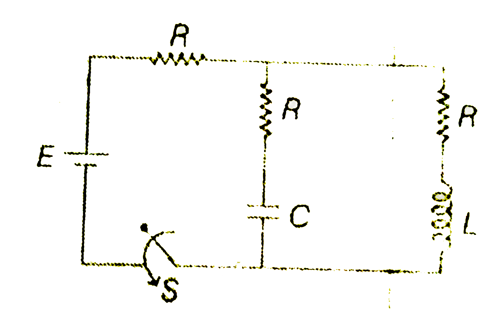
A
B
C
D
Text Solution
Verified by Experts
The correct Answer is:


Similar Questions
Explore conceptually related problems
Recommended Questions
- In the circuit as shown in the figure, switch S is added at t=0. Then...
Text Solution
|
- In the circuit shown in the figure, switch S is closed at time t=0. Se...
Text Solution
|
- In the circuit shown in figure L=10H, R=5Omega, E=15V. The switch S is...
Text Solution
|
- In the circuit as shown in figure the switch is closed at t = 0 . At t...
Text Solution
|
- In the circuit as shown in figure the switch is closed at t = 0 . A lo...
Text Solution
|
- In the circuit as shown in the figure, switch S is added at t=0. Then...
Text Solution
|
- In the circuit shown in figure switch S is closed at time t=0, which s...
Text Solution
|
- In the circuit diagram shown in figure, initially switch S is opened a...
Text Solution
|
- In the circuit shown in figure switch S is closed at time t=0 Cu...
Text Solution
|