Text Solution
Verified by Experts


Similar Questions
Explore conceptually related problems
Recommended Questions
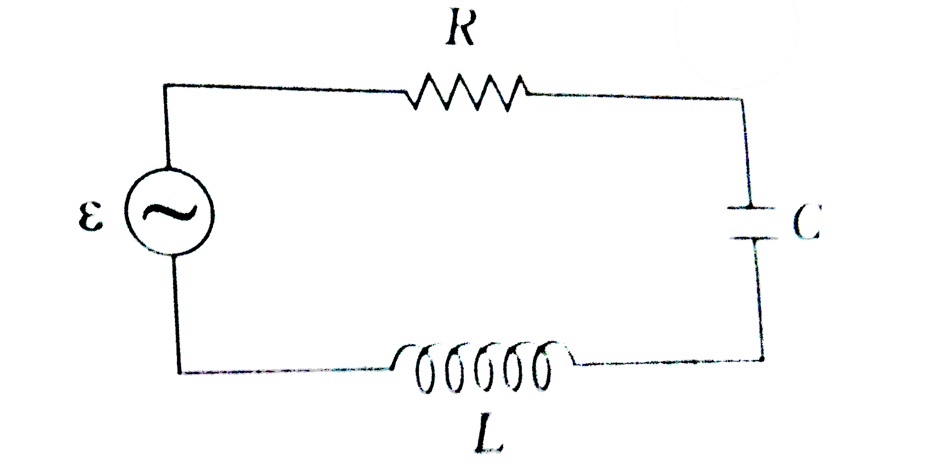
- Figure here, shows a series L-C-R circuit connected to a variable freq...
Text Solution
|
- A series LCR circuit connected to a variable frequency 230 V source ha...
Text Solution
|
- Fig 14.18 shows a series LCR circuit connected to a variable frequency...
Text Solution
|
- Figure here, shows a series L-C-R circuit connected to a variable freq...
Text Solution
|
- Figure shows a series LCR circuit connected to a variable frequency 23...
Text Solution
|
- Figure shows a series LCR circuit connected to a variable frequency 23...
Text Solution
|
- Figure shows a series LCR circuit connected to a variable frequency 23...
Text Solution
|
- Figure shows a series LCR circuit connected to a variable frequency 23...
Text Solution
|
- एक श्रेणी LCR परिपथ में L=10.0H ,C=40 mu F तथा R=60Omega को 240V वो...
Text Solution
|