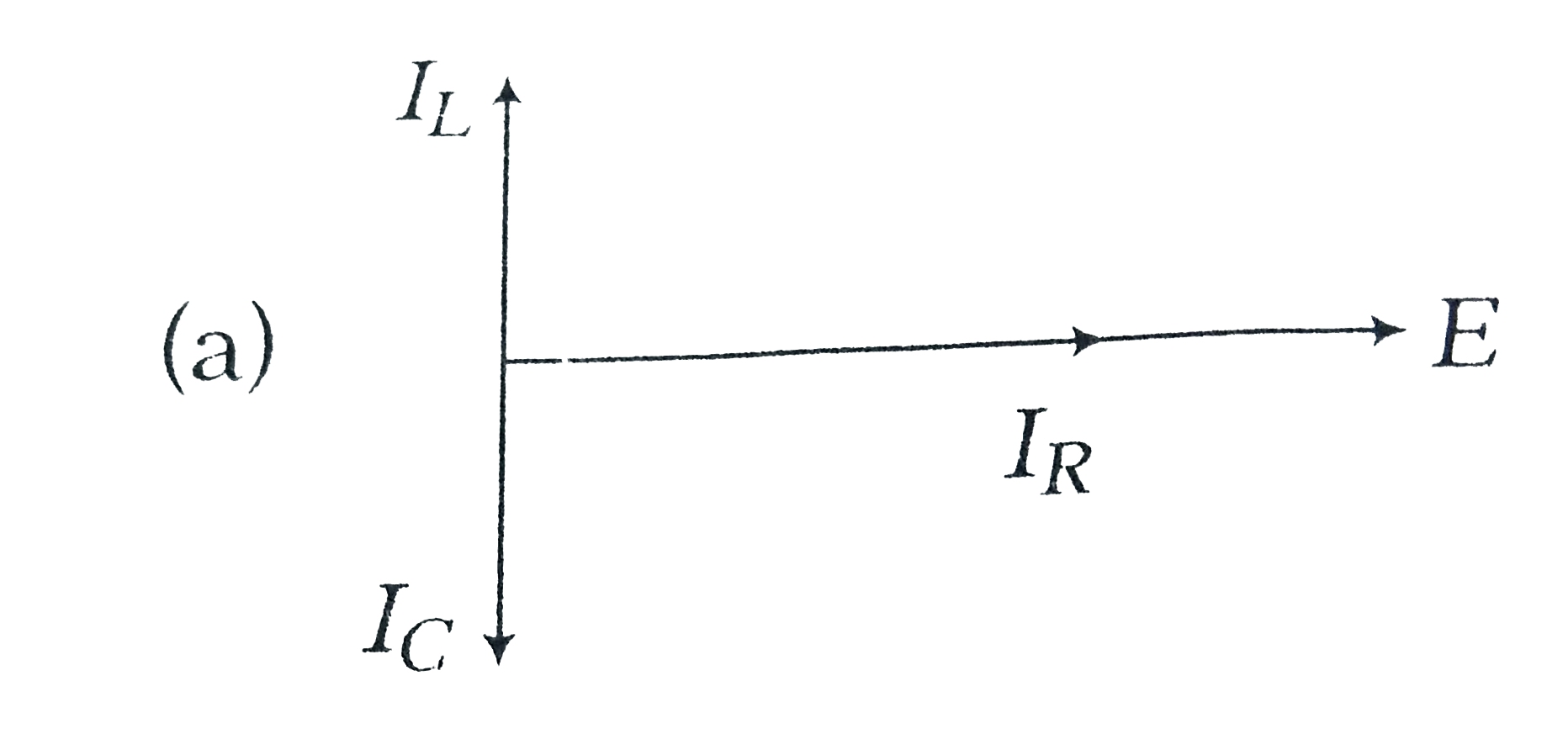
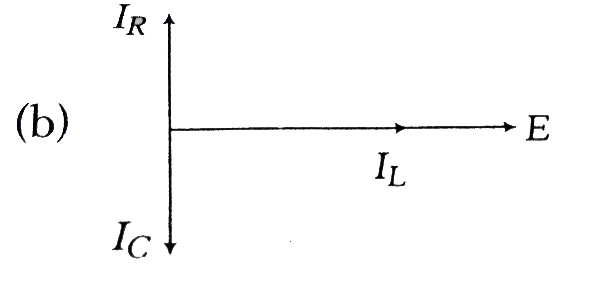
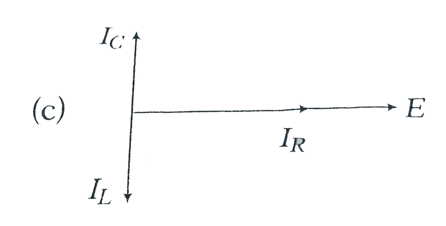
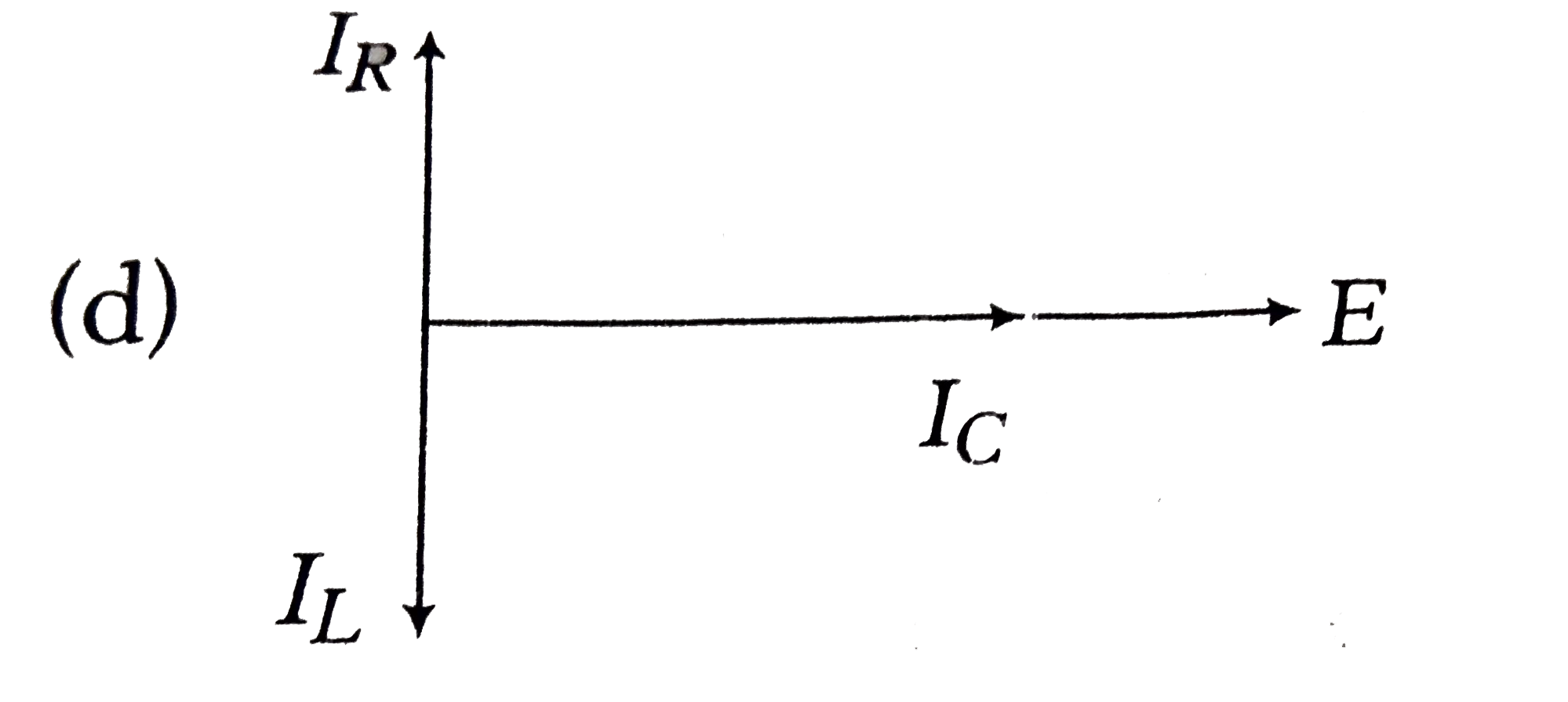
Home
Class 12
PHYSICS
An alternating emf is applied across a p...

An alternating emf is applied across a parallel combination of a resistance R, capacitance C and an inductance L. If `underset(R )(I)`, `underset(L)(I)` and `underset(C )(I)` are the currents through R,L and C respectively, the phase relationship among `underset(R )(I)`, `underset(L)(I)` and `underset(C )(I)` and source emf E, is given by

A

B

C

D

Text Solution

AI Generated Solution

The correct Answer is:
To solve the problem of the phase relationship among the currents through the resistor (IR), inductor (IL), and capacitor (IC) in a parallel AC circuit, we can follow these steps: ### Step-by-Step Solution: 1. **Understand the Circuit Configuration**: - We have a parallel combination of a resistor (R), inductor (L), and capacitor (C) connected to an alternating EMF (E). - In a parallel circuit, the voltage across all components is the same, which is equal to the source EMF (E). 2. **Identify the Current Relationships**: - The current through the resistor (IR) is in phase with the EMF (E). This means that the phasor for IR is aligned with the phasor for E. - The current through the capacitor (IC) leads the voltage across it (E) by 90 degrees (or π/2 radians). - The current through the inductor (IL) lags the voltage across it (E) by 90 degrees (or π/2 radians). 3. **Draw the Phasor Diagram**: - Start by drawing the phasor for the EMF (E) along the horizontal axis (real axis). - Draw the phasor for the current through the resistor (IR) along the same direction as E since they are in phase. - Draw the phasor for the current through the capacitor (IC) vertically upwards (positive y-axis) because it leads the EMF by π/2. - Draw the phasor for the current through the inductor (IL) vertically downwards (negative y-axis) because it lags the EMF by π/2. 4. **Analyze the Phasor Relationships**: - From the phasor diagram, we can see that: - IR is along the same direction as E. - IC is along the positive y-axis. - IL is along the negative y-axis. - This indicates the phase relationships: - IR (in phase with E) - IC (leads E by π/2) - IL (lags E by π/2) 5. **Select the Correct Option**: - Based on the analysis and the phasor diagram, we can conclude that the correct option representing the phase relationship among IR, IL, IC, and E is the one that matches our findings. ### Final Answer: The correct option for the phase relationship among IR, IL, IC, and the source EMF E is **Option C**.

To solve the problem of the phase relationship among the currents through the resistor (IR), inductor (IL), and capacitor (IC) in a parallel AC circuit, we can follow these steps: ### Step-by-Step Solution: 1. **Understand the Circuit Configuration**: - We have a parallel combination of a resistor (R), inductor (L), and capacitor (C) connected to an alternating EMF (E). - In a parallel circuit, the voltage across all components is the same, which is equal to the source EMF (E). ...
Promotional Banner

Similar Questions

Explore conceptually related problems

An ideal resistance R, ideal inductance L , ideal capacitance C and AC voltmeters underset(1)(V) , underset(2)(V) , underset(3)(V) and underset(4)(V) are connected to an AC source as shown . At resonance

Two inductors underset(1)(L) and underset(2)(L) are connected in parallel and a time varying current flows as shown in figure. Then the ratio currents underset(1)(l) / underset(2)(l) at any time t is

A circuit contains resistance R and an inductance L in series. An alternating voltage V=V_0sinomegat is applied across it. The currents in R and L respectively will be .

A circuit contains resistance R and an inductance L in series. An alternating voltage V=V_0sinomegat is applied across it. The currents in R and L respectively will be .

An L-C-R series is under resonance . If underset(m)(l) is current amplitude underset(m)(V) is voltage amplitude, R is the resonance , Z is the impedance , underset(L)(X) is the inducitve reactance and underset( C )(X) is the capacitive reactance , then

For series L-C-R circuit shown in the figure, the readings of underset(2)(V) and underset(3)(V) are same and each equal to 100 V .Then

In underset((i))(-NO_(2)) ,underset((ii))( -NH_(2)) , underset((iii))(-SO_(3)H) , The decreasing order of -I effect is

Figures shows a parallel LCR circuit connected to a 200V, AC source. L=5H, C=80muF and R=40Omega . At resonance let I_(1) and i_(2) be the rs currents through L,C and R. Then

The correct IUPAC name of the given compound is I-underset(F)underset(|)(C)=underset(Cl)underset(|)(C)-C-=C-OCH_(2)

The reaction R-underset(O)underset(||)C-R underset(H_2SO_4)overset(N_3 H)rarrRCONHR + N_2 is called