Text Solution
Verified by Experts


Similar Questions
Explore conceptually related problems
Recommended Questions
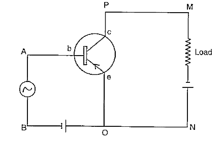
- Figure below shows the circuit of an electronic device : (i) Whic...
Text Solution
|
- The phase difference between input and output voltage of a CE circuit ...
Text Solution
|
- In common emitter transistor amplifier circuit, the input signal volta...
Text Solution
|
- In a common emitter amplifier the load resistance of the output circui...
Text Solution
|
- A full wave rectifier circuit along with the input and output voltages...
Text Solution
|
- CE प्रवर्धक परिपथ में निवेश तथा निर्गत वोल्टेज में कलान्तर होता है
Text Solution
|
- In an ideal step down transformer, the input voltage is 400V and the o...
Text Solution
|
- For a transistor circuit in common emitter configuration, the voltage ...
Text Solution
|
- Draw a circuit diagram of a CE amplifier by using n-p-n transistor and...
Text Solution
|