Home
Class 12
PHYSICS
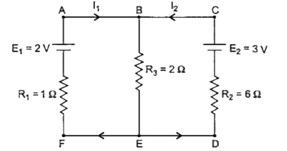
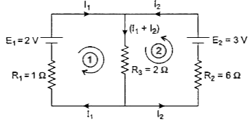
In the circuit shown in figure below, E1...

In the circuit shown in figure below, `E_1` and `E_2` are two cells having emfs 2 V and 3 V respectively, and negligible internal resistances. Applying Kirchhoff.s laws of electrical networks, find the values of currents `I_1` and `I_2`.
 

Text Solution

Verified by Experts


Consider the direction of currents as shown in the figure above.
By applying Kirchhoff.s second law in mesh (1), we get
`R_3(I_1  + I_2) + R_1I_1 - E_1 = 0`
`2(I_1 + I_2) + 1 xxI_1 = 2`
`implies 3I_ + 2I_2 = 2 " " ...(1)`
By applying Kirhchoff.s second law in mesh (2), we get ,
`R_3 (I_1 + I_2) + R_2I_2 - E_2 = 0`
`2(I_1 + I_2) + 6I_2 = 3`
`implies 2I_1 + 8I_2 = 3 " " ...(2)`
On solving equations( 1) and (2) , we get
`I_1 = 1/2 A and I_2 = 1/4 A`.
Promotional Banner

Similar Questions

Explore conceptually related problems

In the circuit given, E_(1) "and" E_(2) are two cells emfs 4 V and 6 V respectively, having negligible internal resistance. Applying Kirchhoff.s law of electrical networks, find the values of I_(1) "and" I_(2) .

In the circuit shown in figure below, E_(1) and E_(2) are batteries having emfs 4.0 V and 3.5 V respectively and internal resistance 1Omega and 2Omega respectively. Using Kirchhoff.s laws, calculate currents : I_(1),I_(2) and I_(3) .

In the circuit shown E, F, G and H are cells of emf 2V, 1V, 3V and 1V respectively and their internal resistance are 2Omega, 1Omega, 3Omega and 1Omega respectively.

In the circuit shown E, F, G and H are cells of emf 2V, 1V, 3V and 1V respectively and their internal resistance are 2Omega, 1Omega, 3Omega and 1Omega respectively.

In the circuit shown in figure ,find the ratio of currents i_(1)//i_(2).

In the circuit shown in figure-3.391, V_(1) and V_(2) are two voltmeters having resistances 6000 Omega and 4000 Omega respectively EMF of battery is 250V, having negligible internal resistance. Two resistances R_(1) and R_(2) are 4000 Omega and 6000 Omega respectively. Find the reading of the voltamter V_(1) and V_(2) when (a) Switch S is open ltbgt (b) Switch S is closed

Using kirchhoff.s law of electrical networks , calculate the currents l_1 , l_2 and l_3 in the circuit shown below .

Statement I: In the potentiometer circuit shown in figure. E_1 and E_2 are the emf of cells C_1 and C_2 , repsectively, with E_1gtE_2 . Cell C_1 has negligible internal resistance. For a given resistor R, the balance length is x. If the diameter of the potentiometer wire AB is increased, the balance length x will decrease. Statement II: At the balance point, the potential difference between AD due to cell C_1 is E_2 , the emf of cell C_2 .

In the circuit shown in fig. the cell has emf 10V and internal resistance 1 Omega

epsi_(1) and epsi_(2) are two batteries having e.m.f of 34V and 10V respectively and internal resistance of 1Omega and 2Omega respectively. They are connected as shown in figure below. Using Kirchhoff.s Laws of electrical networks, calculate the current I_(1) and I_(2)