A
B
C
D
Text Solution
Verified by Experts
The correct Answer is:


Similar Questions
Explore conceptually related problems
Recommended Questions
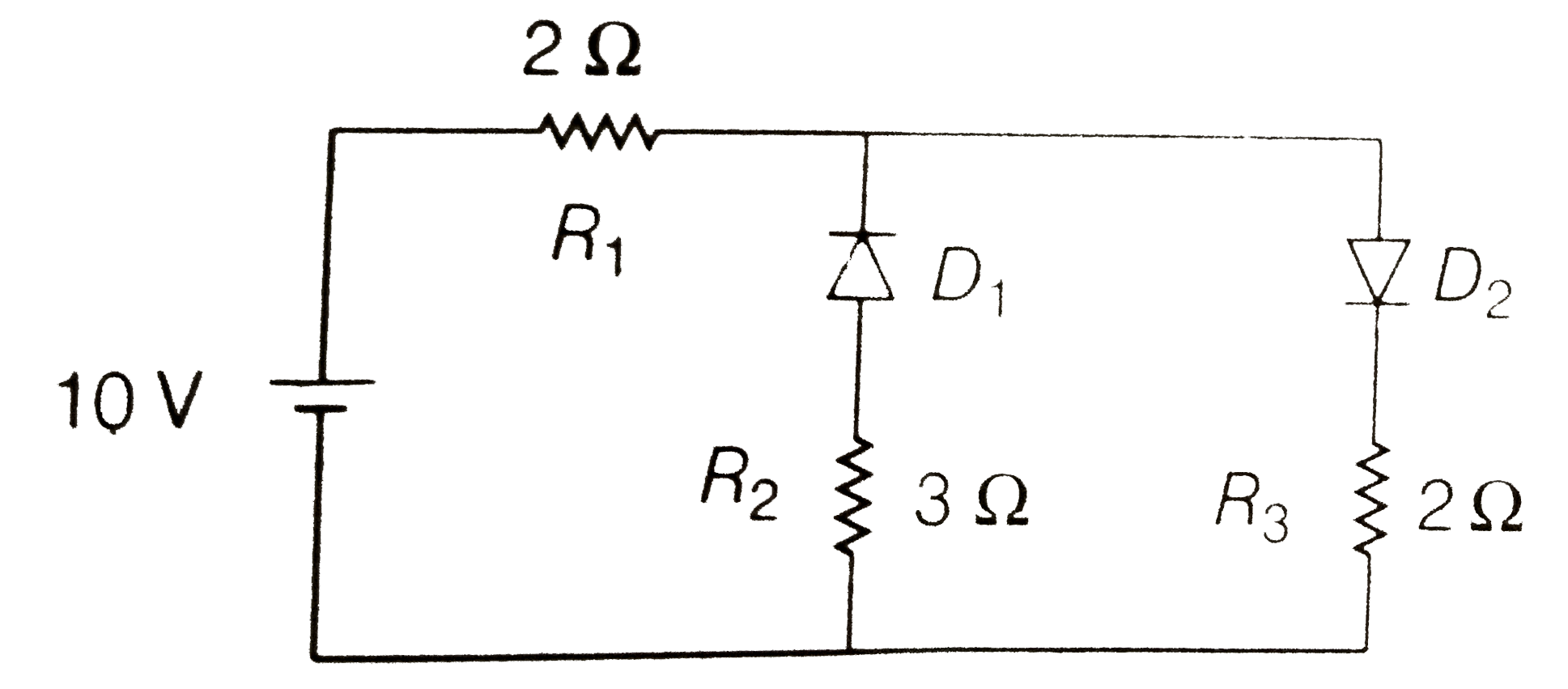
- The given circuit has two ideal diodes connected as shown in the figur...
Text Solution
|
- The given circuit has two ideal diodes connected as show in the figure...
Text Solution
|
- For the circuit shown in Fig., find the current flowing through the 1O...
Text Solution
|
- 4 ideal diodes are connected as shown in the circuit the current throu...
Text Solution
|
- An ideal diode and a 5 fl resistor are connected in series with a 15 V...
Text Solution
|
- The given circuit has two ideal diodes connected as shown in figure be...
Text Solution
|
- In ideal junction diode as shown in figure the current flowing through...
Text Solution
|
- The given circuit has two ideal diodes connected as show in the figure...
Text Solution
|
- Calculate the current flowing in the circuit below which has two oppos...
Text Solution
|