A
B
C
D
Text Solution
Verified by Experts
The correct Answer is:


Similar Questions
Explore conceptually related problems
Recommended Questions
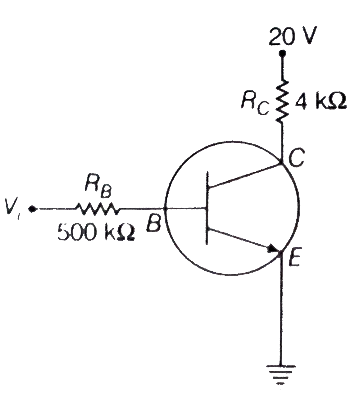
- In the circuit shown in the figure, the input voltage V(i) is 20V, V(B...
Text Solution
|
- In the circuit shown in the figure, the input voltage V(i) is 20V,V(BE...
Text Solution
|
- In the circuit shown in Fig. if we assume that when the input volta...
Text Solution
|
- In the circuit shown in Fig. when the input voltage of the base resist...
Text Solution
|
- For the transistor circuit shown in figure , evaluate VE , RB and RE. ...
Text Solution
|
- In the accompanying circuit (Fig. 5.9) the value of beta is 100 . Find...
Text Solution
|
- In the circuit shown in the figure, the input voltage V(i) is 20V, V(B...
Text Solution
|
- दिए गए परिपथ आरेख में निवेश वाल्टता (Vi) 20 वाल्ट, V(BE) = 0 तथा V(C...
Text Solution
|
- In the circuit shows in the figure, the input voltage V(i) is 20 V,...
Text Solution
|