Text Solution
Verified by Experts


Similar Questions
Explore conceptually related problems
Recommended Questions
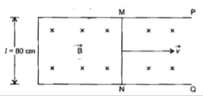
- Figure 1 below shows a metallic rod MN of length l= 80cm, kept in a un...
Text Solution
|
- A conducting rod of length l slides at constant velocity v on two para...
Text Solution
|
- A rod of length l is moving velocity v "in magnetic field" b as seen i...
Text Solution
|
- A rod lies acrossfrictionless rails in a uniform magnetic field vec(B)...
Text Solution
|
- A rod of length l is moved horizontally with a uniform velocity v in a...
Text Solution
|
- A metal rod of length I is moved with velocity v in a uniform magnetic...
Text Solution
|
- A copper rod of length l rotates an angular velocity omega in a unifor...
Text Solution
|
- A conducting rod of length l is rotating with constant angular velocit...
Text Solution
|
- A metallic rod of length l is moved perpendicular to its length with v...
Text Solution
|