


Similar Questions
Explore conceptually related problems
Recommended Questions
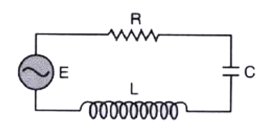
- The figure shows a series LCR circuit connected to a varriable of 200 ...
Text Solution
|
- A series LCR circuit with L = 80 mH, C = 50 mu F and R = 60 ohm is con...
Text Solution
|
- Figures shows a parallel LCR circuit connected to a 200V, AC source. L...
Text Solution
|
- Figure shows a series LCR circuit connected to a variable frequency 23...
Text Solution
|
- Figure shows a series LCR circuit connected to a variable frequency 23...
Text Solution
|
- A series LCR circuit is connected to a variable frequency 230 V source...
Text Solution
|
- A series LCR circuit is connected to a variable frequency 230 V source...
Text Solution
|
- In a series LCR circuit R=25Omega,L=10 mH and C=1muF. The circuit is c...
Text Solution
|
- चित्र में एक श्रेणीबद्ध LCR परिपथ दिखलाया गया है जिसे परिवर्ती आवृत्ति...
Text Solution
|