Text Solution
Verified by Experts


Similar Questions
Explore conceptually related problems
Recommended Questions
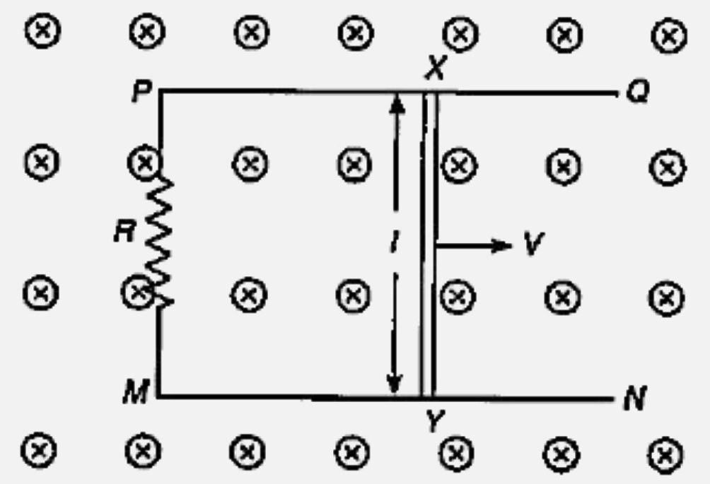
- PQ and MN are two parallel conductors at a distance l apart and connec...
Text Solution
|
- In Figure, it is given that L M=M N ,\ Q M=M R ,\ M L\ |P Q\ a n d\ ...
Text Solution
|
- In Fig.44, it is given that L M=M N ,\ Q M=M R ,\ M L|P Q\ and\ ...
Text Solution
|
- Find the current in the wire PQ for the configuration shown in Fig. Wi...
Text Solution
|
- A conducting wire MN carrying a current I is bent into the shape as sh...
Text Solution
|
- Two parallel fixed conducting rails are l distance apart. They are con...
Text Solution
|
- A conductor PQ, carrying a current i is placed perpendicular to a long...
Text Solution
|
- l दूरी पर स्थित PQ तथा MN हो समान्तर चालक एक प्रतिरोध R के साथ जुड़े है...
Text Solution
|
- यह दिया है कि LM=MN,QM=MR,ML bot PQतथा MN bot PR, तो सिध्द करो कि PQ=P...
Text Solution
|