 .
.Text Solution
Verified by Experts


Topper's Solved these Questions
CAPACITOR AND CAPACITANCE
CENGAGE PHYSICS ENGLISH|Exercise Subjective|24 VideosCAPACITOR AND CAPACITANCE
CENGAGE PHYSICS ENGLISH|Exercise Single Correct|49 VideosCAPACITOR AND CAPACITANCE
CENGAGE PHYSICS ENGLISH|Exercise Exercise 4.1|13 VideosATOMIC PHYSICS
CENGAGE PHYSICS ENGLISH|Exercise ddp.4.3|15 VideosCENGAGE PHYSICS DPP
CENGAGE PHYSICS ENGLISH|Exercise subjective type|51 Videos
Similar Questions
Explore conceptually related problems
CENGAGE PHYSICS ENGLISH-CAPACITOR AND CAPACITANCE-Exercise 4.2
- A parallel plate vacuum capacitor eith plate area A and separation x h...
Text Solution
|
- You have two identical capacitors and an external potential source. ...
Text Solution
|
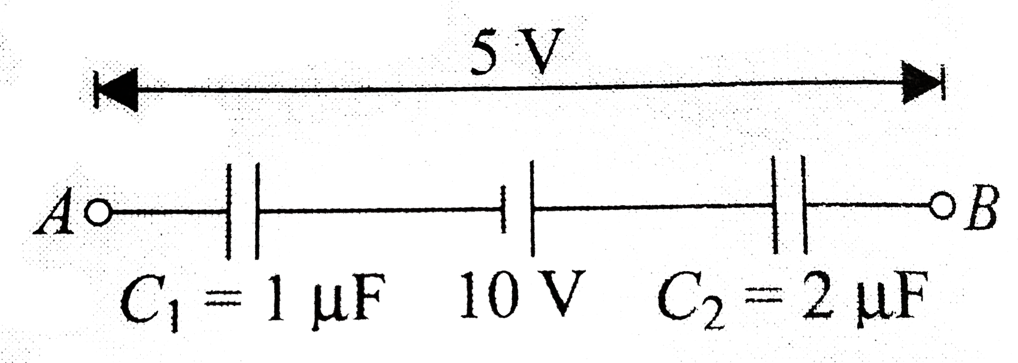
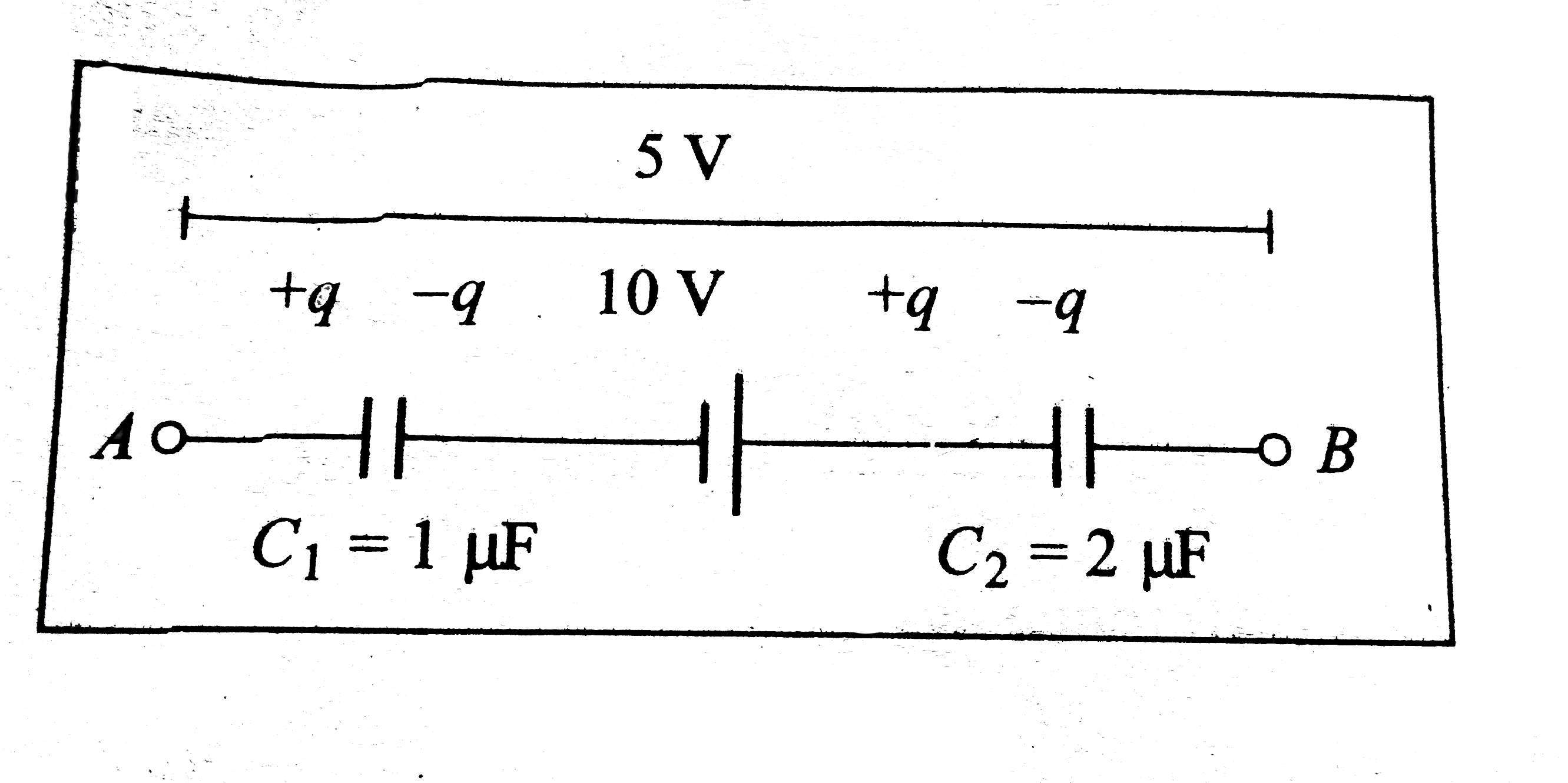
- A circuit has section AB as shown in The emf of the cell is 10 V, and ...
Text Solution
|
- While a capacitor remains connected to a battery a dielectic slab is s...
Text Solution
|
- If you have several 2.0 muF capacitrors, each capable of withstanding ...
Text Solution
|
- n identical capacitors are connected in parallel to a potential differ...
Text Solution
|
- In the arrangement shwn in Fig.4.96, plate (B) given a charge equal t...
Text Solution
|
- In plate A has 100 muC charge, while plate B has 60 muC charge. a....
Text Solution
|
- For the network of capacirors as shown in figure. . a. Find the p...
Text Solution
|
- In the system is in steady state. Then a. V(A)-V(B)="" b. V(B)-V(C...
Text Solution
|
- Find whether the following statements are true or false. a. If a bat...
Text Solution
|
- Find the equicalent capacitance between points A and B as show in .
Text Solution
|
- Three capacitors C(1),C(2) and C(3) are connected as shown in, The pot...
Text Solution
|
- Find charge supplied by the bettery in the arrangement shown in figur...
Text Solution
|
- Two large parallel metal plates, each having area A, are oriented hori...
Text Solution
|
- A 10 muF capacitor is charged to 15 V. It is next connected in seties ...
Text Solution
|
- Consider the situation shown in figure (31-E23 ) . The switch S is ope...
Text Solution
|
- Figure shows two identical parallel plate capacitors connected to a sw...
Text Solution
|
- Four parallel large plates separated by equal distance d are arranged ...
Text Solution
|
- Find the charges on the three capacitors shown in figure
Text Solution
|