Text Solution
Verified by Experts


Topper's Solved these Questions
ELECTRIC CURRENT AND CIRCUIT
CENGAGE PHYSICS ENGLISH|Exercise Subjective|29 VideosELECTRIC CURRENT AND CIRCUIT
CENGAGE PHYSICS ENGLISH|Exercise Single Correct|72 VideosELECTRIC CURRENT AND CIRCUIT
CENGAGE PHYSICS ENGLISH|Exercise Exercise 5.1|28 VideosELECTRIC CURRENT & CIRCUITS
CENGAGE PHYSICS ENGLISH|Exercise Kirchhoff s law and simple circuits|15 VideosELECTRIC FLUX AND GAUSS LAW
CENGAGE PHYSICS ENGLISH|Exercise MCQ s|38 Videos
Similar Questions
Explore conceptually related problems
CENGAGE PHYSICS ENGLISH-ELECTRIC CURRENT AND CIRCUIT-Exercise 5.2
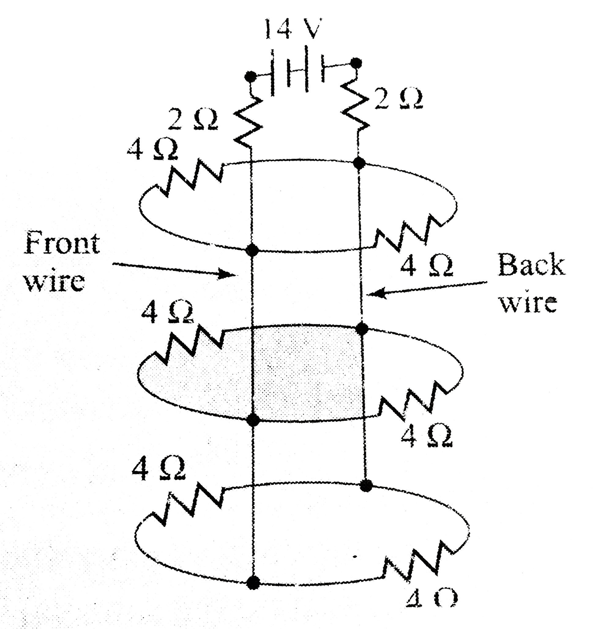
- Calculate the resistance between the terminals A and B of the network ...
Text Solution
|
- In the ciruit the cells E1 and E2 have emfs of 4V and 8V and internal ...
Text Solution
|
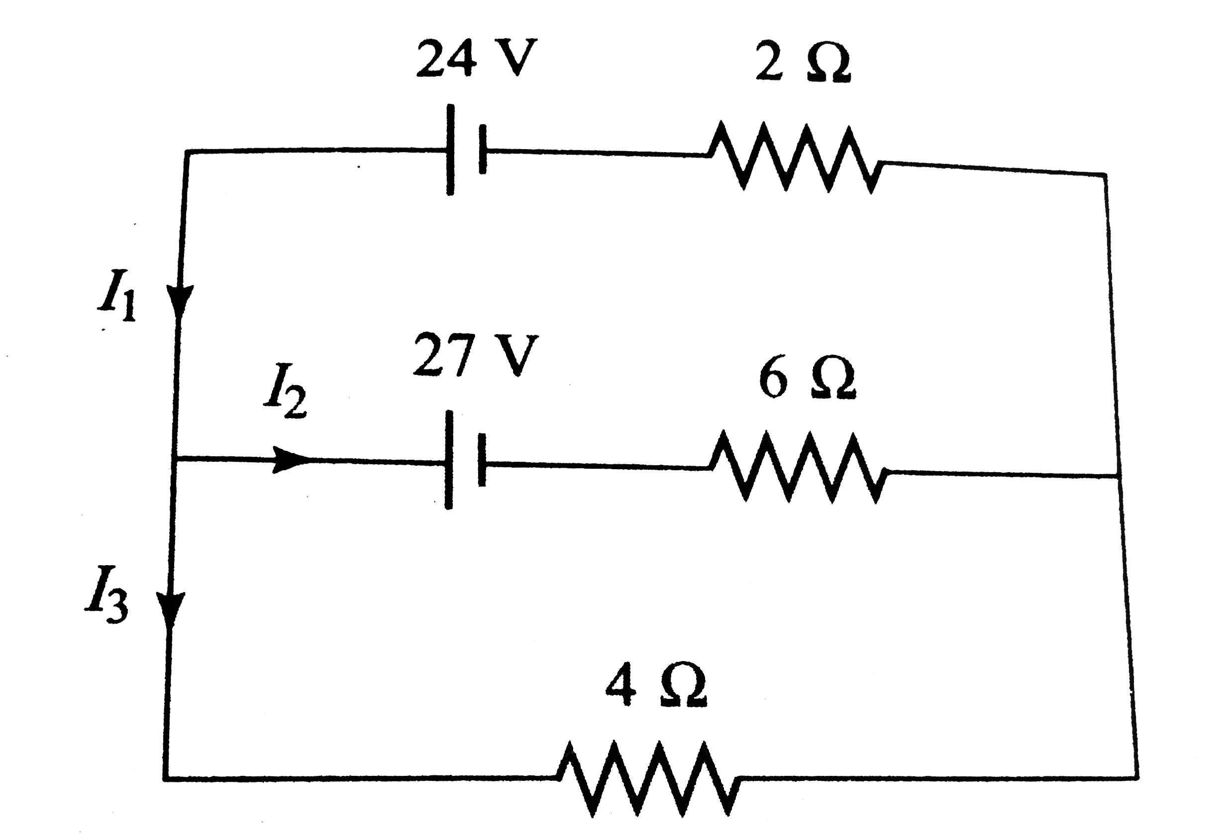
- Determine the currents I1, I2, and I3 for the network shown below ...
Text Solution
|
- Find the current supplied by the source in fig the resistors are mount...
Text Solution
|
- A parallel combination of an 8 Omega resistor and an unknown resistor ...
Text Solution
|
- For the resistor network shown in the potential drop between a and b s...
Text Solution
|
- For the circuit in find the potential difference between points a and...
Text Solution
|
- Find the current in each resistor of the circuit shown in fig a. Cu...
Text Solution
|
- Given that a current of 5.0 A passes along the branch from C to B is f...
Text Solution
|
- The diagram shows a circuit used in an experiment to determine the emf...
Text Solution
|
- Each resistance in the circuit is of 2000 Omega. The combinatios i...
Text Solution
|
- Consider the circuits shown in fing Both the circuits are taking same ...
Text Solution
|
- Calculate the current through the resistance connected across MN and t...
Text Solution
|
- In this given figure find the equivalent resistance across AB.
Text Solution
|
- Each of the resistance in the network shown in the figure is equal to ...
Text Solution
|
- A battery of emf 2.0 volts and internal resistance 0.10(Omega)is being...
Text Solution
|
- How a battery is to be connected so that the shown rheostat will behav...
Text Solution
|
- In the following circuit ,E1 = 4V, R1 = 2 Omega, E2 = 6 V, R2 = 2Ome...
Text Solution
|
- Consider the cicutir shown in fig. the current i3 is equal to
Text Solution
|
- In the follwing circuit , the potential difference betweenn P and Q si
Text Solution
|