Home
Class 12
PHYSICS
In the cicuit shown in fig. C is a paral...

In the cicuit shown in fig. C is a parallel plate air capacitor having plate of area `A = 50cm^2` each and distance d = 1mm apart. `R_1 R_2, and R_3` are resistors having resistance `3Omega, 2Omega, and 1Omega` respectively. Two identical sources each of emf V and of emf V and of negligible internal resistance are connected as shown in fig. if a dielectric strength of are is `E_0 = 3xx10^6Vm^(-10)`, calculate the maximum safe value of V.

Text Solution

Verified by Experts

Due to sources, currents flow
through resistance `R_(1),R_(2)` and
`R_(3)` and capacitor gets charged.
Due to charge, an electic field
is established in the capacitor
whose magnitude cannot
exceed dielectric strength `E_(0)`
of air. Maximum safe value of
V corresponds to the maximum
possible charge on capacitor.
Let the Maximum
possibel charge on capacitor be `q_(0)` then the electic field inside
the capacitor is `E_(0) = q_(0)//A epsilon_(0),`
Then the electirc field inside
the capacitor is `E_(0) = q_(0)//A epsilon_(0),`
where `q_(0) A epsilon_(0)E_(0) = 15,000 epsilon_(0) and C = epsilon_(0) A//d = 5epilon_(0)` farad
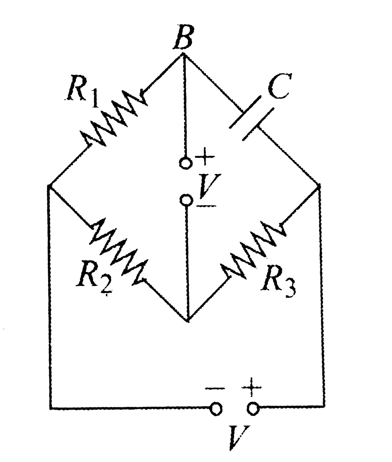
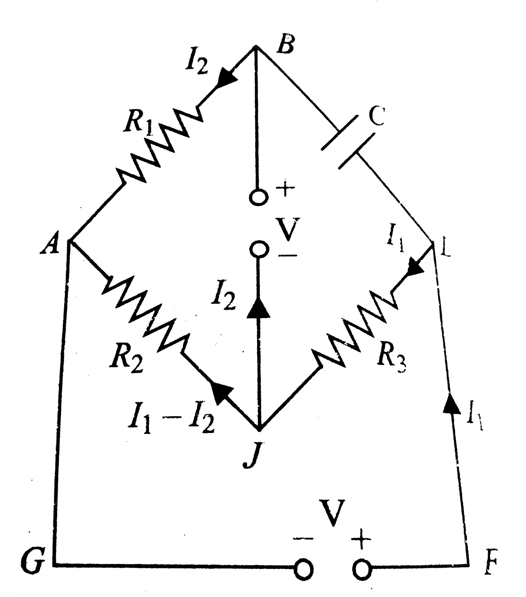
Since, in steady state, no current flows through the capacitor
current through various parts of the circuit will be as sown in
fig. Now we analyze the cirucit in a steady state. First applying Kirchhoff's voltage law on mesh ABJA, we get
`I_(2)R_(1) + V +R_(2)(I_(1) - I_(2)) = 0 or 2I_(1) -5I_(2) = -V` (i)
For mesh AJDFGA,
`-R_(2)(I_(1) - I_(2))-R_(3)I_(1) +V = 0 or eI_(1) - 2I_(2) = V` (ii)
From Eqs. (i) and (ii): `I_(1) = (7V)/(11)` and `I_(2) = (%V)/(11)`
Now applying Kirchhoff's voltage law on mesh BDJB, we get
`(q)/(C) +I_(1) R_(3) - V = 0 or or q= (4CV)/(11) = (20)/(11) epsilon_(0)V`
But the maximum possible value of q is `q_(0) = 15,000 epsilon_(0).` Therefore, the maximum safe value of V is `11q_(0)//20epsilon_(0) = 8250V = 8.25kV.`
Promotional Banner

Topper's Solved these Questions

  • ELECTRIC CURRENT AND CIRCUIT

    CENGAGE PHYSICS ENGLISH|Exercise Single Correct|72 Videos
  • ELECTRIC CURRENT AND CIRCUIT

    CENGAGE PHYSICS ENGLISH|Exercise Multiple Correct|16 Videos
  • ELECTRIC CURRENT AND CIRCUIT

    CENGAGE PHYSICS ENGLISH|Exercise Exercise 5.2|50 Videos
  • ELECTRIC CURRENT & CIRCUITS

    CENGAGE PHYSICS ENGLISH|Exercise Kirchhoff s law and simple circuits|15 Videos
  • ELECTRIC FLUX AND GAUSS LAW

    CENGAGE PHYSICS ENGLISH|Exercise MCQ s|38 Videos

Similar Questions

Explore conceptually related problems

Three resistors of resistances 3Omega, 4Omega and 5Omega are combined in parallel. This combination is connected to a battery of emf 12V and negligible internal resistance, current through each resistor in ampere is

Two indentical batteries, each of emf 2V andinternal resistance r=1Omega are connected as shown. The maximum power that can be developed across R using these batteries is

Eight cells marked 1 to 8, each of emf 5 V and internal resistance 0.2 Omega are connected as shown. What is the reading of ideal voltmeter ?

In the circuit shown in fig. the cell has emf 10V and internal resistance 1 Omega

Two resistors of resistances 2Omega and 6Omega are connected in parallel. This combination is then connected to a battery of emf 2 V and internal resistance 0.5 Omega . What is the current flowing through the battery ?

24 cells, each of emf 1.5V and internal resistance is 2Omega connected to 12Omega series external resistance. Then,

In the circuit shown E, F, G and H are cells of emf 2V, 1V, 3V and 1V respectively and their internal resistance are 2Omega, 1Omega, 3Omega and 1Omega respectively.

In the circuit shown E, F, G and H are cells of emf 2V, 1V, 3V and 1V respectively and their internal resistance are 2Omega, 1Omega, 3Omega and 1Omega respectively.

Two ideal batteries of emf V_1 and V_2 and three resistances R_1, R_2 and R_3 are connected as shown in the figure. The current in resistance R_2 would be zero if

Two batteries, one of emf 18V and internal resistance 2Omega and the other of emf 12 and internal resistance 1Omega , are connected as shown. The voltmeter V will record a reading of

CENGAGE PHYSICS ENGLISH-ELECTRIC CURRENT AND CIRCUIT-Subjective
  1. The circuit shown in fig 5.223 is in steady state. find the charges ...

    Text Solution

    |

  2. Consider an infinita ladder of network shown In fig 5.223A voltage is ...

    Text Solution

    |

  3. For a circuit shown in figure 5.235 switch S1 is closed at t= 0, then ...

    Text Solution

    |

  4. Find the potential difference between the plates of the capactior C in...

    Text Solution

    |

  5. Analyze the given circuit in the steady state condition. Charge on the...

    Text Solution

    |

  6. (a) What is the potential of point a with respect to point b in figure...

    Text Solution

    |

  7. In the cicuit shown in fig. C is a parallel plate air capacitor having...

    Text Solution

    |

  8. The circuit shown in fig. Is in steady state. i. Find the energy...

    Text Solution

    |

  9. The given R-C circuit has two swithes S1 and S2 Swithc S2 is clsoed a...

    Text Solution

    |

  10. For the circuit arrangement shown in fig. a. Find the potentail d...

    Text Solution

    |

  11. The plates of a capacitor of capacitance C are given the charges Q1 an...

    Text Solution

    |

  12. Consider a parallel pate capacitor of capactance C with partially cond...

    Text Solution

    |

  13. The switch S is closed aty t = 0. the capacitor C is uncharged but C0 ...

    Text Solution

    |

  14. Only switch S1 closed in fig. a. what is the steady-state reading of...

    Text Solution

    |

  15. A point charge +q is moved with a constant velocity v toward a solid c...

    Text Solution

    |

  16. Calculate equivalent resistance between A and B of the circuit shown i...

    Text Solution

    |

  17. In the circuit shown in fig. calculate the following: a. Potential d...

    Text Solution

    |

  18. In the given cirucit, determine current through branch having indicate...

    Text Solution

    |

  19. Determine current through batteries epsilon(1) and epsilon(2)

    Text Solution

    |

  20. The cirucit shown in fig. extends to the right into infinity. Each bat...

    Text Solution

    |