A
B
C
D
Text Solution
Verified by Experts
The correct Answer is:


Topper's Solved these Questions
ELECTRIC CURRENT AND CIRCUIT
CENGAGE PHYSICS ENGLISH|Exercise Multiple Correct|16 VideosELECTRIC CURRENT AND CIRCUIT
CENGAGE PHYSICS ENGLISH|Exercise Comprehension|35 VideosELECTRIC CURRENT AND CIRCUIT
CENGAGE PHYSICS ENGLISH|Exercise Subjective|29 VideosELECTRIC CURRENT & CIRCUITS
CENGAGE PHYSICS ENGLISH|Exercise Kirchhoff s law and simple circuits|15 VideosELECTRIC FLUX AND GAUSS LAW
CENGAGE PHYSICS ENGLISH|Exercise MCQ s|38 Videos
Similar Questions
Explore conceptually related problems
CENGAGE PHYSICS ENGLISH-ELECTRIC CURRENT AND CIRCUIT-Single Correct
- find the equivalent resistance between A and E(resistance of each resi...
Text Solution
|
- The circuit shown has resistor of equal resistance R. Find the equival...
Text Solution
|
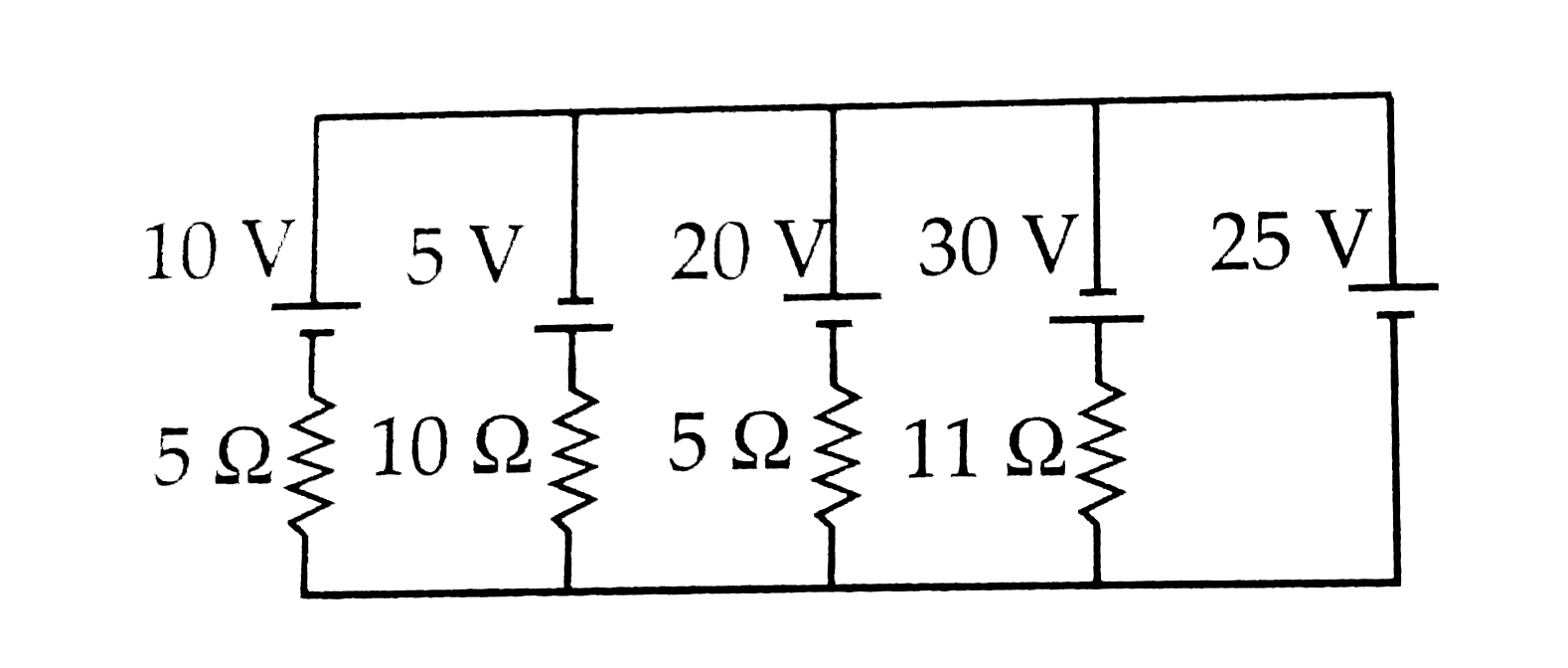
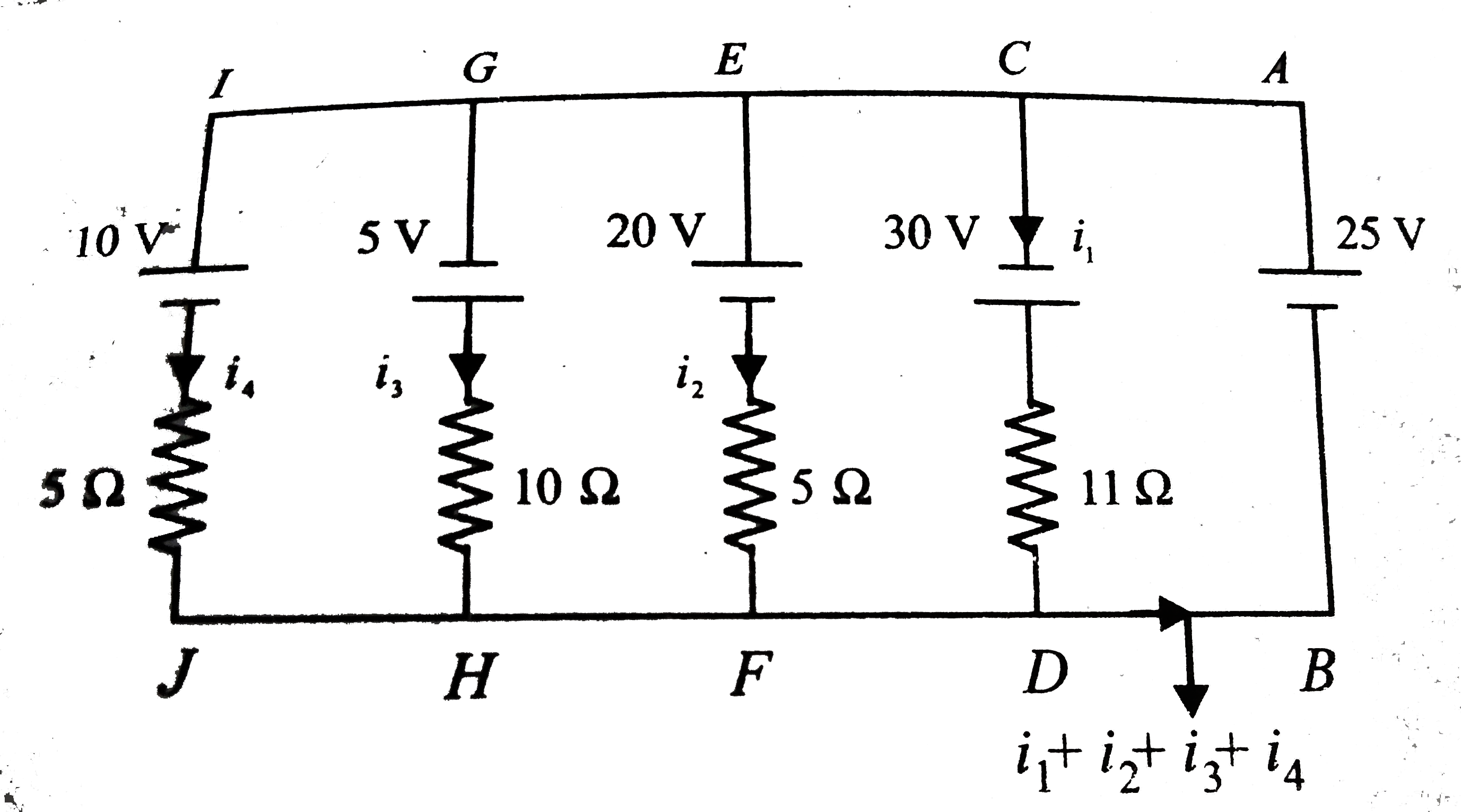
- In the circuit shown, current flowing through 25 V cell is
Text Solution
|
- Figure represents a load consisting of three identical resistances con...
Text Solution
|
- In the circuit shwon in fig. the current I has a value equal to
Text Solution
|
- Figure 5.260 shows two square, X and Y cut from a sheet of metal of un...
Text Solution
|
- The magnitude and direction of the current in the circuit shown will b...
Text Solution
|
- A cell ofemf E volt with no internal resistance is connected to a wire...
Text Solution
|
- The plot represents the flow of current through a wire at three differ...
Text Solution
|
- In the network shown, the equivalent resistance between A and B is
Text Solution
|
- In the circuit shown in fig. 5.265, E1 = E2 = E3 = 2V and R1 = R2 = 4O...
Text Solution
|
- Resistance of a wire at temperature t^(@)C is R = R(0)(1+at+bt^(2)) ...
Text Solution
|
- The masses of the three wires of copper are in the ratio of 1:3:5 and ...
Text Solution
|
- In the part of a circuit shown in fig. 5.266, the potential difference...
Text Solution
|
- In fig , after closing switch S, what is the change in curent flowing ...
Text Solution
|
- In the above question, what would have been the change in current in A...
Text Solution
|
- The emf of a cell is epsilon and its internal resistance is r. its ter...
Text Solution
|
- N identical calls are cannected to from a battery. When the terminals...
Text Solution
|
- n identical cells, each of emf epsilon and internal resistance r, are ...
Text Solution
|
- n identical cells, each of emf epsilon and internal resistance r, are ...
Text Solution
|