A
B
C
D
Text Solution
Verified by Experts
The correct Answer is:


Topper's Solved these Questions
MISCELLANEOUS VOLUME 3
CENGAGE PHYSICS ENGLISH|Exercise Interger Answer type|20 VideosMISCELLANEOUS VOLUME 3
CENGAGE PHYSICS ENGLISH|Exercise Fill in the blanks|10 VideosMISCELLANEOUS VOLUME 3
CENGAGE PHYSICS ENGLISH|Exercise Assertion and Reason Type|8 VideosMAGNETIC FIELD AND MAGNETIC FORCES
CENGAGE PHYSICS ENGLISH|Exercise Multiple Correct Answer type|2 VideosMISCELLANEOUS VOLUME 5
CENGAGE PHYSICS ENGLISH|Exercise Integer|12 Videos
Similar Questions
Explore conceptually related problems
CENGAGE PHYSICS ENGLISH-MISCELLANEOUS VOLUME 3-Comprehension Type
- In a certain experiments to measure the ratio of charge to mass of ele...
Text Solution
|
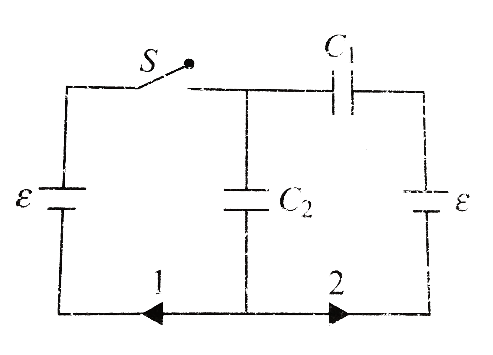
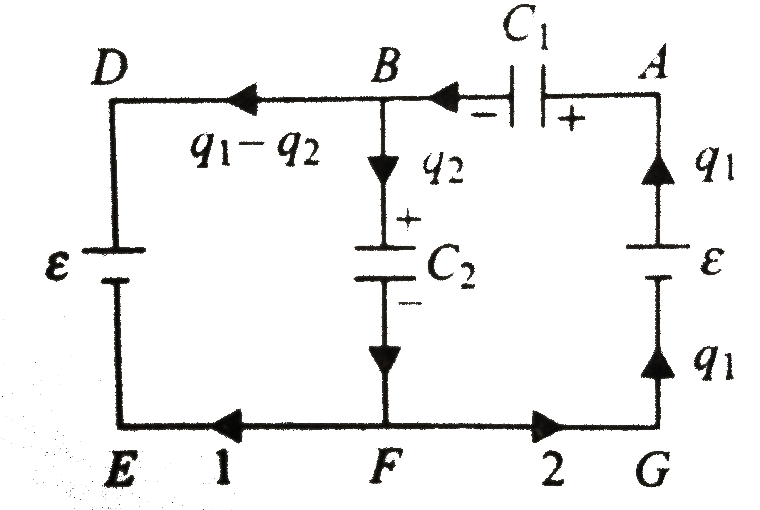
- In the circuit shown in figure initially the switch is opened. The swi...
Text Solution
|
- In the circuit shown in figure initially the switch is opened. The swi...
Text Solution
|
- Capacitor C1 = 2 muF and C2 = 3muF are connected in series to a batter...
Text Solution
|
- Capacitor C1 = 2 muF and C2 = 3muF are connected in series to a batter...
Text Solution
|
- Capacitor C1 = 2 muF and C2 = 3muF are connected in series to a batter...
Text Solution
|
- A researcher studying the properties of ions in the upper atmosphere w...
Text Solution
|
- A researcher studying the properties of ions in the upper atmosphere w...
Text Solution
|
- A point charge q1 is placed inside cavity 1 and another point charge q...
Text Solution
|
- A point charge q1 is placed inside cavity 1 and another point charge q...
Text Solution
|
- A point charge q1 is placed inside cavity 1 and another point charge q...
Text Solution
|
- A point charge q1 is placed inside cavity 1 and another point charge q...
Text Solution
|
- A point charge q1 is placed inside cavity 1 and another point charge q...
Text Solution
|
- Four concentric hollow spheres of radii R, 2R, 3R, and 4R are given th...
Text Solution
|
- Four concentric hollow spheres of radii R, 2R, 3R, and 4R are given th...
Text Solution
|
- Four concentric hollow spheres of radii R, 2R, 3R, and 4R are given th...
Text Solution
|
- Four concentric hollow spheres of radii R, 2R, 3R, and 4R are given th...
Text Solution
|
- Three metallic plates out of which the middle is given charge Q as sho...
Text Solution
|
- Three metallic plates out of which the middle is given charge Q as sho...
Text Solution
|
- Three metallic plates out of which the middle is given charge Q as sho...
Text Solution
|