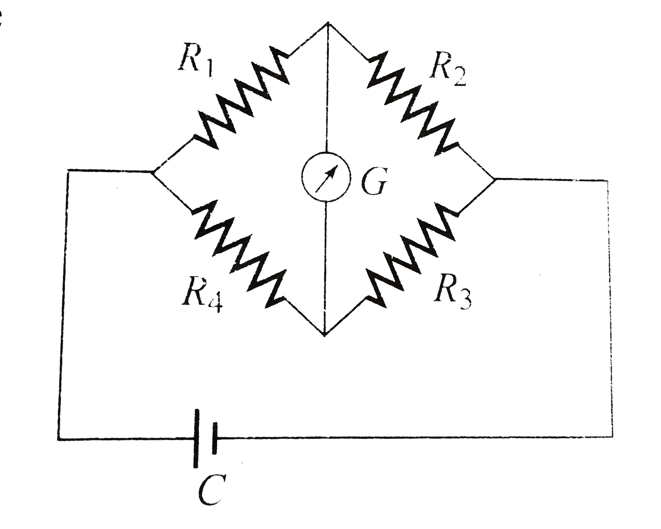
Home
Class 12
PHYSICS
The Wheatstone's bridge shown in the Fig...

The Wheatstone's bridge shown in the Fig. A2.5 is balanced. If the positions of the cell C and the galvanometer F are now interchanged, G will show zero deflection

A

in all cases

B

only if all the resistances

C

only if `R_1 = R_3 and R_2= R_1`

D

only if `R_1//R_3 = R_2//R_4`

Text Solution

Verified by Experts

The correct Answer is:
A

a. In a Wheatstone bridge, the deflection in the galvanometer does not change if the battery and galvanometer are interchanged.
Promotional Banner

Similar Questions

Explore conceptually related problems

If in the experiment of Wheatstone's bridge, the positions of cells and galvanometer are interchanged, then balance point will

In a wheatstone bridge if the battery and galvanometer are interchanged then the deflection in galvanometer will

In the circuit shown in Fig., the cell is ideal with e.m.f = 2V. The resistance of the coil of the galvanometer G is 1Omega . Then

For the potentiometer arrangement shown in the figure, length of wire AB is 100 cm and its resistance is 9 Omega . Find the length AC for which the galvanometer G will show zero deflection.

The potentiometer wire AB shown in figure is 40 cm long. Where should the free end of the galvanometer be connected on AB so that the galvanometer may show zero deflection?

The Wheatstone bridge shown in Fig. here, gets balanced when the carbon resistor used as R_(1) has the colour code (Orange, Red, Brown). The resistors R_(2) and R_(4) are 80 Omega and 40 Omega , respectively. Assuming that the colour code for the carbon resistor, used as R_(3) , would be:

In the meter bridge experiment, balance point was observed at J with AJ=I. (i) The values of R and X were doubled and then interchanged. What would be the new position of balance point (ii) If the galvanometer and battery are interchanged at the balance position, how will the balance point get affected?

The potentiometer wire AB shown in figure is 40 cm long. Where the free end of the galvanometer should be connected on AB so that the galvanometer may show zero deflection?

Two inductors of self inductances L_(1) and L_(2) and of resistances R_(1) and R_(2) (not shown) respectively are conneted in the circuit as shown. At the instant t = 0, key k is closed. Obtain an expression for which the galvanometer will show zero deflection at all times after the key is closed.

The given Wheatstone bridge is showing no deflection in the galvanometer joined between the points B and D in fig Find the value of R