A
B
C
D
Text Solution
Verified by Experts
The correct Answer is:


Similar Questions
Explore conceptually related problems
Recommended Questions
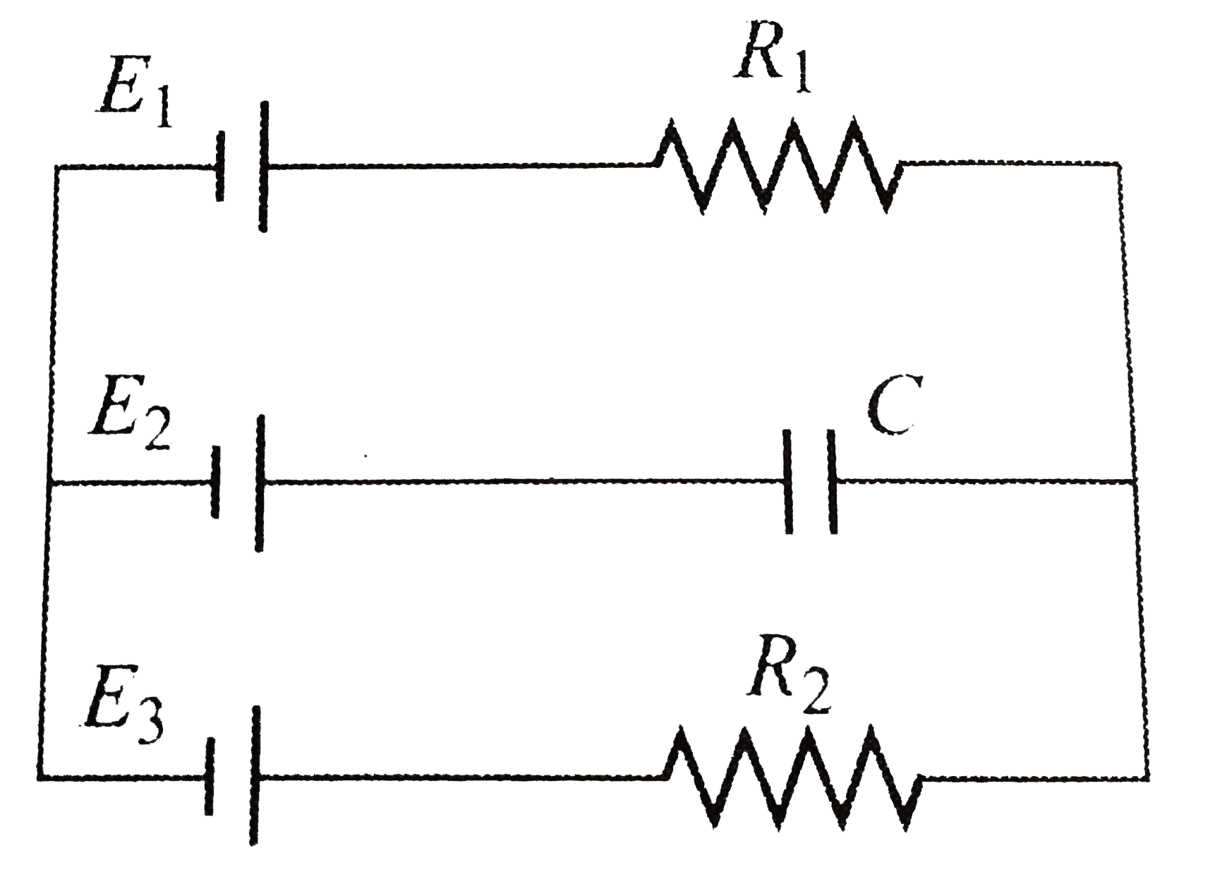
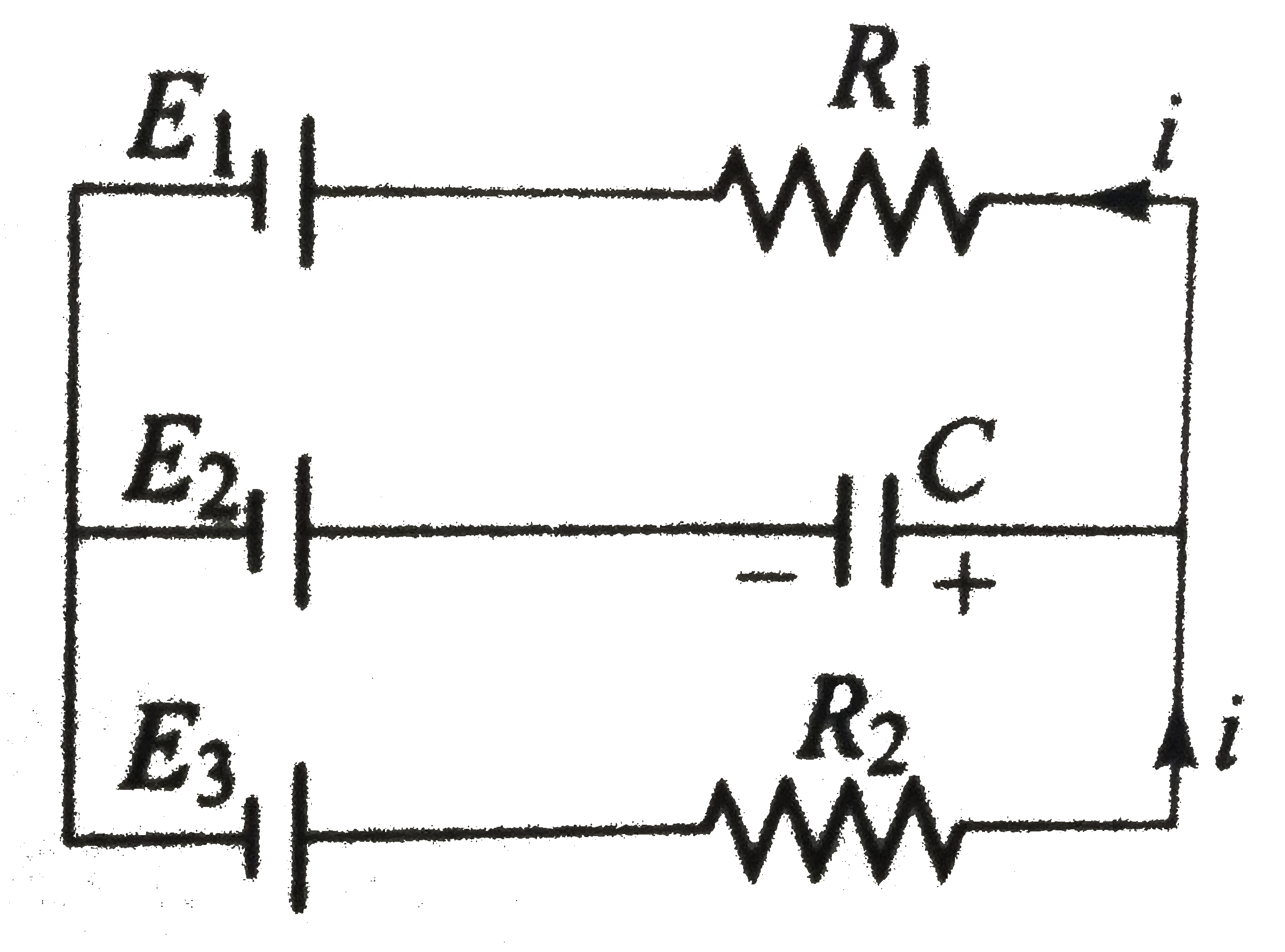
- In the circuit shown , the batteries have emf E1 = E2= 1V , E3 = 2.5 V...
Text Solution
|
- In the circuit shown in fig. 5.265, E1 = E2 = E3 = 2V and R1 = R2 = 4O...
Text Solution
|
- For the batteries shown in fig. R1, R2 and R3 are the internal resista...
Text Solution
|
- In the circuit shown , the batteries have emf E1 = E2= 1V , E3 = 2.5 V...
Text Solution
|
- Figure shows a battery with emf 15 V in a circuit with R1 = 30Omega, R...
Text Solution
|
- The circuit consists of two resistors (of resistance R(1) = 20 Omega a...
Text Solution
|
- For the circuit shown, with R1=1.0 Omega,R2=2.0Omega,E1=2V and E2=E3...
Text Solution
|
- 4 muF के एक संधारित्र को परिपथ में दिखाए गए अनुसार जोड़ा जाता है। बैटर...
Text Solution
|
- यहाँ दर्शाये गये परिपथ में E1 = E2 = E3 = 2 वोल्ट तथा R1= R2 =4 Omega ...
Text Solution
|