A
B
C
D
Text Solution
Verified by Experts
The correct Answer is:


Similar Questions
Explore conceptually related problems
Recommended Questions
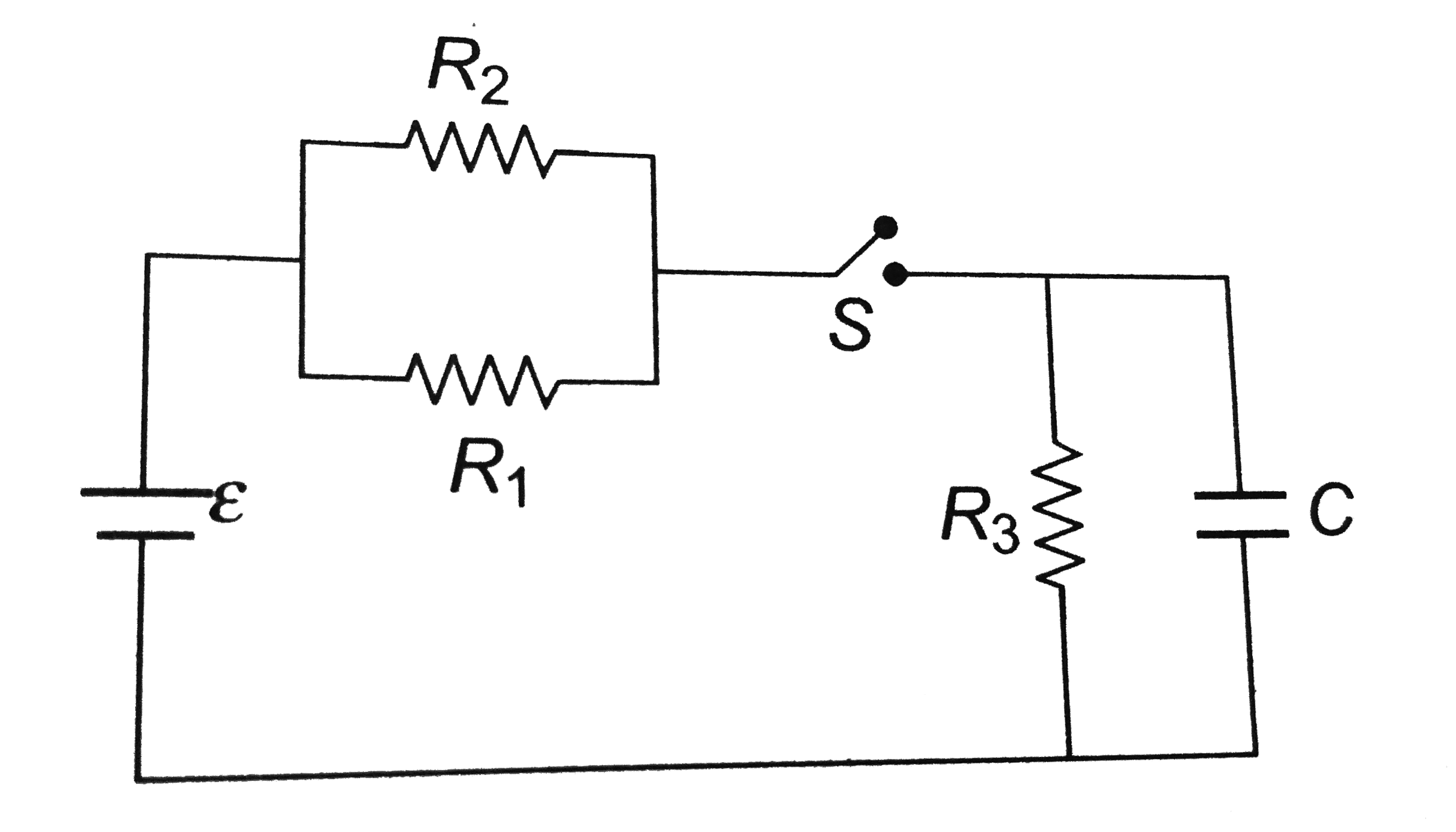
- The circuit shown in the figure consists of a battery of emf epsilon =...
Text Solution
|
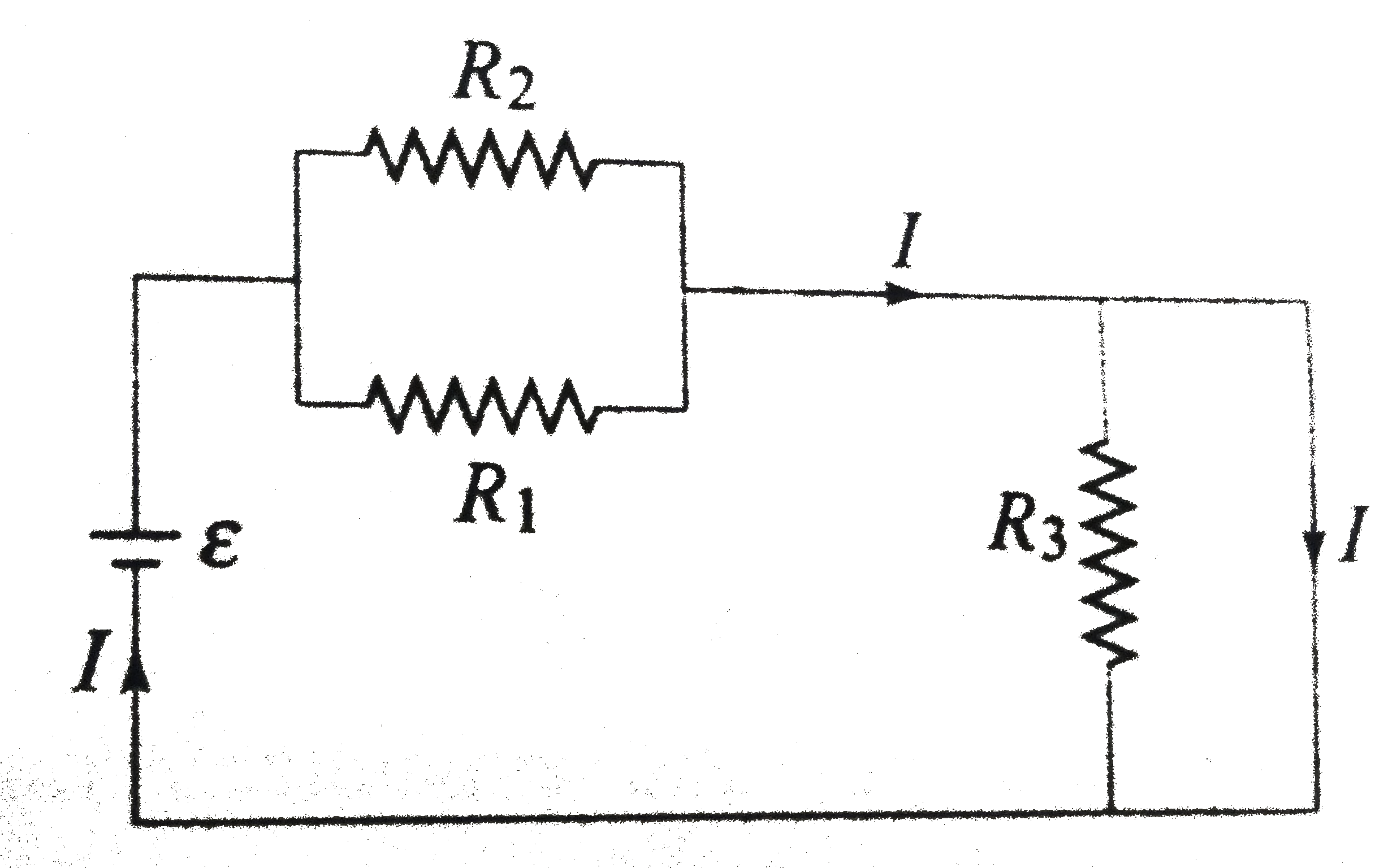
- The figure below shown a battery with emf 15 V in a circuit with R(1) ...
Text Solution
|
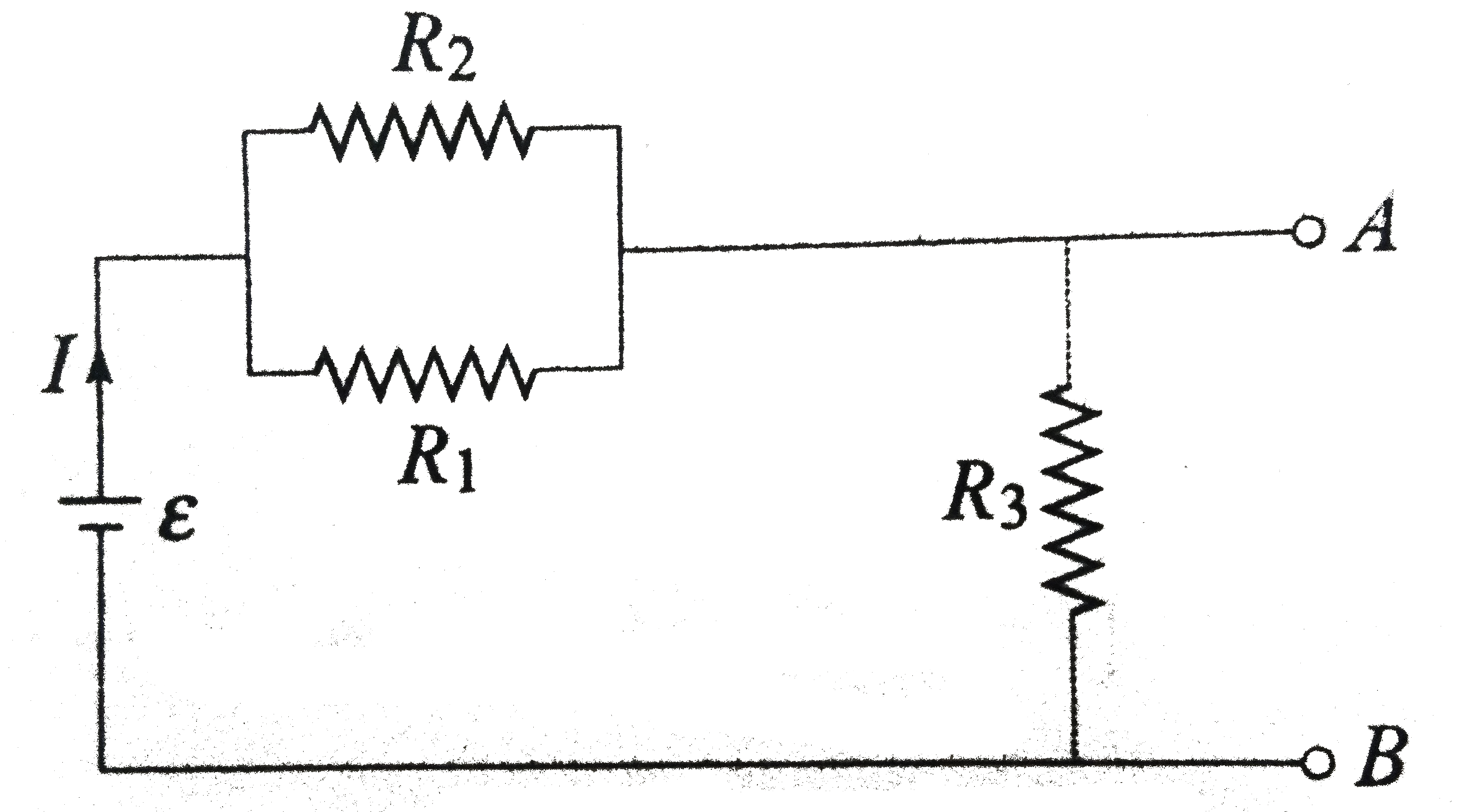
- The circuit shown in the figure consists of a battery of emf epsilon =...
Text Solution
|
- The circuit consists of two resistors (of resistance R(1) = 20 Omega a...
Text Solution
|
- The circuit consists of two resistors (of resistance R(1) = 20 Omega a...
Text Solution
|
- The circuit consists of two resistors (of resistance R(1) = 20 Omega a...
Text Solution
|
- In the circuit shown in the figure R(1) =3 Omega,R(2) = 2 Omega and R(...
Text Solution
|
- In the connection shown in the figure the switch K is open and the cap...
Text Solution
|
- A capacitor of capacitance 6 mu F and initial charge 1.60 muC is conne...
Text Solution
|