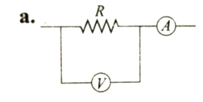
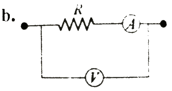
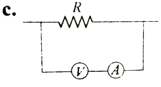
Home
Class 12
PHYSICS
Which of the following circuits gives th...

Which of the following circuits gives the correct value of resistance, when computed by using `R = (V//I)` where V and I are voltmeter and ammeter reading, respectively? The meters are not ideal.

A

B

C

D

none of these

Text Solution

AI Generated Solution

The correct Answer is:
To solve the problem of determining which circuit gives the correct value of resistance using the formula \( R = \frac{V}{I} \), where \( V \) is the voltmeter reading and \( I \) is the ammeter reading, we need to analyze the behavior of the ammeter and voltmeter in different circuit configurations. ### Step-by-Step Solution: 1. **Understand the Concept**: - The formula \( R = \frac{V}{I} \) gives the correct resistance value only if \( V \) is the potential difference across the resistor and \( I \) is the current flowing through that same resistor. 2. **Consider Non-Ideal Meters**: - Since the meters are not ideal, they have finite resistances. Let \( R_a \) be the resistance of the ammeter and \( R_v \) be the resistance of the voltmeter. This means that both meters will affect the circuit operation. 3. **Analyze Circuit Cases**: - **Case 1**: If the voltmeter is connected in parallel with the resistor: - The voltmeter will draw some current \( I' \) due to its resistance \( R_v \). - The current flowing through the resistor will then be \( I - I' \) (where \( I \) is the total current). - The voltmeter will read the voltage across both the resistor and its own resistance, which will not give the correct voltage across the resistor alone. - Thus, \( R = \frac{V}{I} \) will not yield the correct resistance. - **Case 2**: If the ammeter is connected in series with the resistor: - The ammeter will read the total current \( I \) flowing through the circuit. - However, the voltmeter will measure the voltage drop across both the resistor and the ammeter's resistance \( R_a \). - Therefore, the voltmeter reading \( V \) will not be the voltage across the resistor alone, leading to \( R = \frac{V}{I} \) not giving the correct resistance. - **Case 3**: If the ammeter is connected in parallel with the resistor: - The ammeter will not measure the current flowing through the resistor, as it is bypassed. - This configuration is incorrect for measuring resistance since the ammeter will read a different current than what flows through the resistor. 4. **Conclusion**: - In all analyzed cases, the configurations do not yield the correct resistance value when using \( R = \frac{V}{I} \) due to the non-ideal nature of the meters and their placements in the circuit. - Therefore, the answer is that none of the circuits provide the correct value of resistance.

To solve the problem of determining which circuit gives the correct value of resistance using the formula \( R = \frac{V}{I} \), where \( V \) is the voltmeter reading and \( I \) is the ammeter reading, we need to analyze the behavior of the ammeter and voltmeter in different circuit configurations. ### Step-by-Step Solution: 1. **Understand the Concept**: - The formula \( R = \frac{V}{I} \) gives the correct resistance value only if \( V \) is the potential difference across the resistor and \( I \) is the current flowing through that same resistor. 2. **Consider Non-Ideal Meters**: ...
Promotional Banner

Similar Questions

Explore conceptually related problems

In the series L-C-R circuit , the voltmeter and ammeter readings are respectively

In the circuit shown the reading of ammeter and voltmeter are 4 A and 20 V respectively. The meters are non ideal, then R ia

The value of resistance of an unknown resistor is calculated using the formula R = V//I where V and I are the readings of the voltmeter and the ammeter, respectivley. Consider the circuits below. The internal resistances of the voltmeter and the ammeter (R_V and R_G, respectively) are finite and nonzero. , Let R_(A) and R_(B) be the calculated values in the two cases A and B , respectively. If the resistance of voltmeter is R_(V) = 1k Omega and the percentage error in the measurement of R (the value of R is nearly 10 Omega )is

In the circuit shown in figure neglecting source resistance, the voltmeter and ammeter reading will respectively be

In the circuit shown in figure neglecting source resistance the voltmeter and ammeter reading will respectively, will be

The actual value of resistance R, shown in the figure is 30 Omega . This is measured in an experiment as shown using the standard formula R = (V)/(I) , where V and I are the readings of the voltmeter and ammeter, respectively. If the measured value of R is 5% less, then the internal resistance of the voltmeter is

In the circuit shown, A and V are ideal ammeter and voltmeter respectively. Reading of the voltmeter will be

In the following circuit, determine the reading of ideal voltmeter (V) and ideal ammeter (A).

In the circuit figure, the voltmeter reads 30 V. The resistance of the voltmeter is

In the given circuit, Fig., the reading of voltmeter V_(1) and V_(2) 300 votls each. The reading of the voltemeter V_(3) and ammeter A are respectively