A
B
C
D
Text Solution
Verified by Experts
The correct Answer is:


Similar Questions
Explore conceptually related problems
Recommended Questions
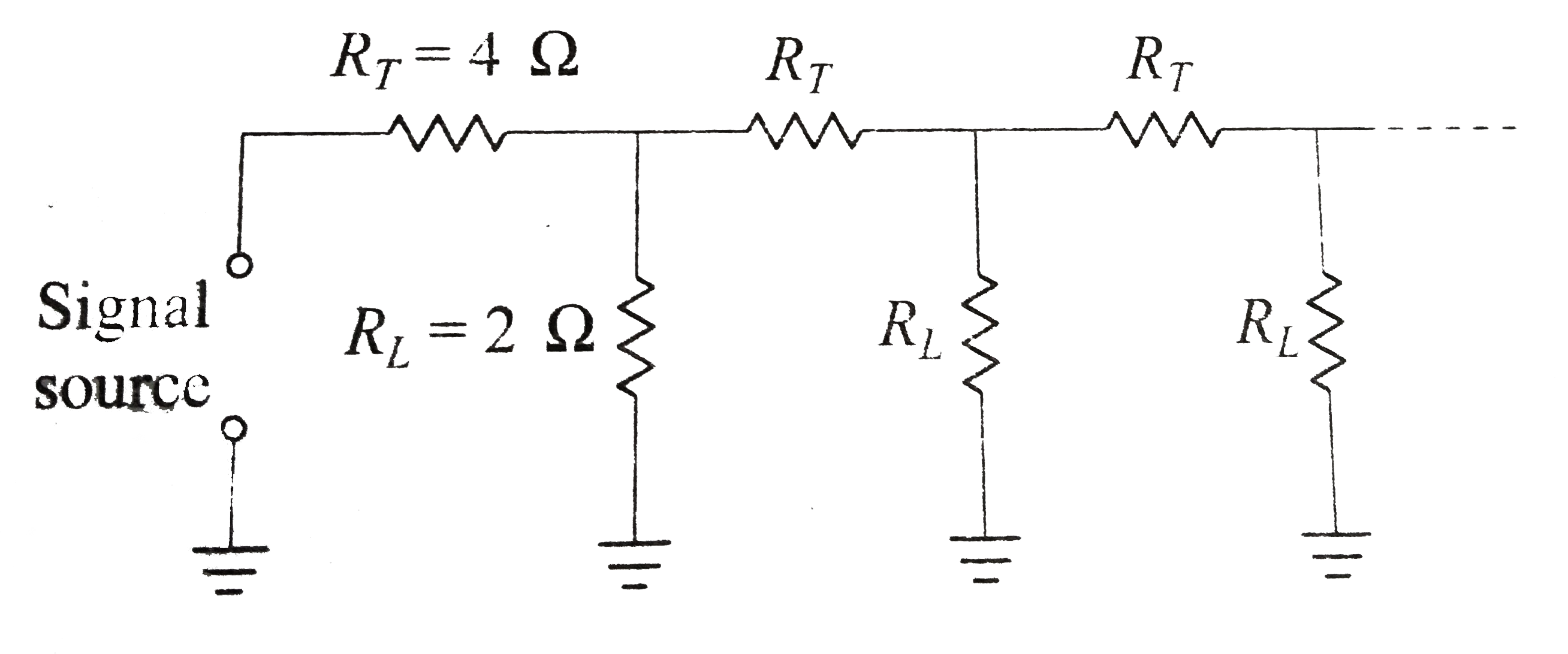
- Figure shows a circuit model for the transmission of an electrical sig...
Text Solution
|
- Figure shows a circuit model for the transmission of an electrical sig...
Text Solution
|
- Thirteen resistances each of resistance R ohm are connected in the cir...
Text Solution
|
- Eight resistances each of resistance 5 Omega are connected in the circ...
Text Solution
|
- For the diode D, the forward resistance is zero and the backward resis...
Text Solution
|
- एक रेडियों प्रसारण केन्द्र के दोलनी परिपथ का प्रेरकत्व 10 mH तथा धारित...
Text Solution
|
- An electrical power line, having a total resistance of 2Omega, deliver...
Text Solution
|
- Thirteen resistances each of resistance R ohm are connected in the cir...
Text Solution
|
- An electrical power line, having a total resistance of 2Omega, deliver...
Text Solution
|