Home
Class 12
PHYSICS
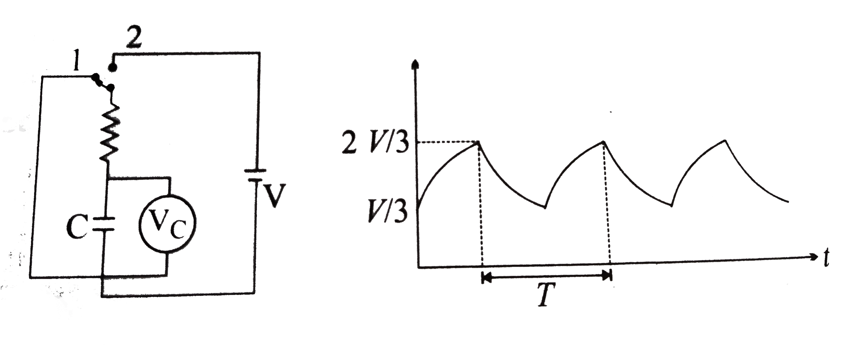
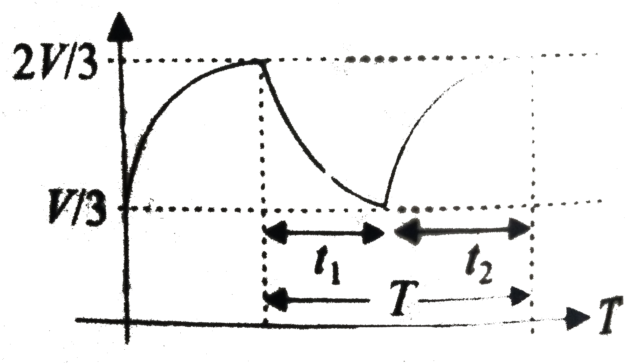
VC is the ideal voltmeter in the figure....

`V_C` is the ideal voltmeter in the figure. Resistance of the resistor shown is R. Initially the switch is in position 2 when charging of the capacitor starts. Initially the capacitor was uncharged. The switch in circuit shifts automatically from 2 to 1 when `V_C gt 2V//3` and goes back to 2 from 1 when `V_C lt V//3`. The ideal voltmeter reads voltage across capacitor as plotted. What is the period T of the wave from in terms of R and C ?
,

A

`3RC 1n 3 `

B

`2 RC 1 n 2`

C

`(RC//2)1n 2`

D

none of these

Text Solution

Verified by Experts

The correct Answer is:
B

b. `t_1` is the time of capacitor to discharge from `2V//3` to `V//3`.
For this , `V/3 = (2V)/2 e^(-t_1//tau)` or `t_1 = tau1n 2 = RC 1n2`
`t_2` is time for charging of capacitor
from `V//3 "to" 2V//3`.
So `int_(VC//3)^(2VC//3) (dq)/(VC-q) = int_(0)^(t_2) (dt)/(RC)`
or `t_2= RC1n 2`
`T = t_1 + t_2 = 2RC 1n 2 `
.
Promotional Banner

Similar Questions

Explore conceptually related problems

The switch in Figure (a) closes when Vc = 2V//3 and opens when Vc = V//3 . The voltmeter reads a voltage as plotted in figure (b). What is the period T of the waveform? (take R_(1) = 6R and R_(2) = 3R , and ln2 = 0.7 if required) (a)

Condsider . In the circuit shown is the switch can be shifted to positions 1 and 2 The charge on capacitor C_(1) when the switch is at position 1 is.

If the reading of the ideal voltmeter shown in the circuit is 2V the internal resistance of the two identical cells is

Initially, the switch is in position 1 for a long time. At t = 0 , the switch is Obtain expressions for V_C and V_R for tgt0

The capacitor C shown in the figure is in steady state condition when switch is shifted from position 1 to position 2.The heat liberated in the process is

The initial charge across capacitors A and B are shown with Q=CE. Find the ratio of final charge in capacitor A to the final charge in capacitor B, when cells are switched on.

In the R-C circuit shown in the figure the total of 3.6 xx 10^(-3)J is dissipated in the 10 ohms resistor when the switch S is closed. The initial charge on the capacitor is

Passage-III In the circuit shown, the battery is ideal with emf V. The capacitor is initially uncharged. The switch is closed at time t = 0 The current in the branch BE at t=oo is

Passage-III In the circuit shown, the battery is ideal with emf V. The capacitor is initially uncharged. The switch is closed at time t = 0 The current in branch containing capacitors at any time t is

In the given figure switch is open initially and capacitor C_2 is unchanged Charge on C2 just after closing the switch is