 .
. A
B
C
D
Text Solution
Verified by Experts
The correct Answer is:
 ,
, 


Similar Questions
Explore conceptually related problems
Recommended Questions
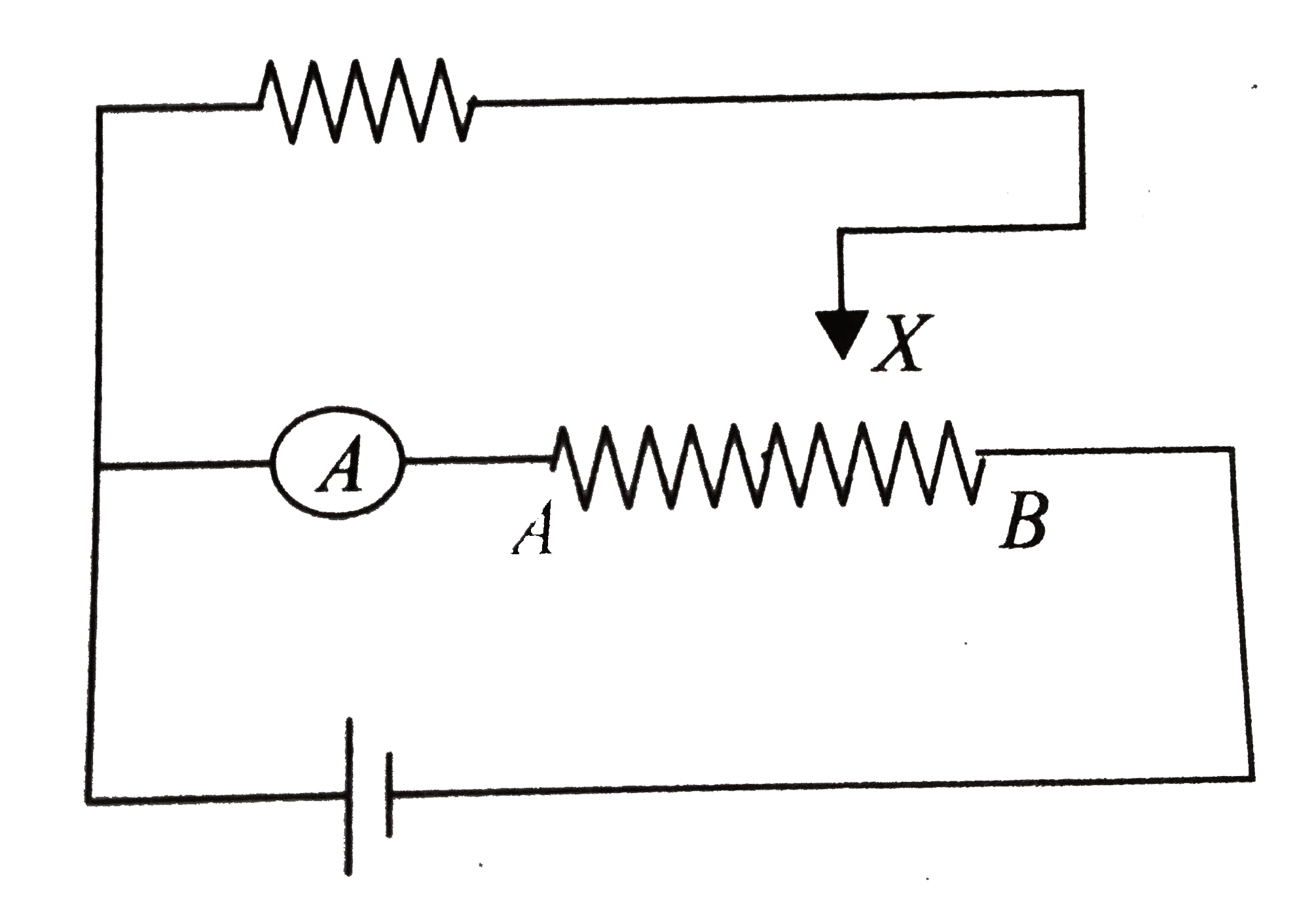
- In circuit shown in figure, terminal X is brought from point A to B. T...
Text Solution
|
- In the circuit shown in figure, reading of ammeter will
Text Solution
|
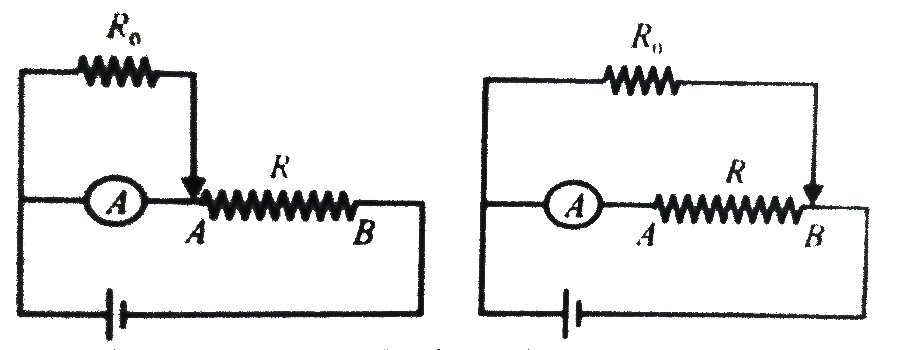
- In circuit shown in figure, terminal X is brought from point A to B. T...
Text Solution
|
- In the circuit shown, the reading of ammeter is:
Text Solution
|
- The reading of ammeter in the circuit shown will be
Text Solution
|
- What is the reading of ideal ammeter (in A ) in the circuit shown in t...
Text Solution
|
- A circuit is shown in the figure. The ratio of readings of ideal voltm...
Text Solution
|
- चित्र में दिखाए परिपथ में अमीटर का पाठयांक क्या होगा।
Text Solution
|
- The reading of ammeter in the circuit shown is
Text Solution
|