 .
.A
B
C
D
Text Solution
Verified by Experts
The correct Answer is:


Similar Questions
Explore conceptually related problems
Recommended Questions
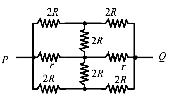
- The effective resistance between points P and Q of the electrical ci...
Text Solution
|
- Two resistances R and 2R are connected in parallel in an electric circ...
Text Solution
|
- The effective resistance between points P and Q of the electrical circ...
Text Solution
|
- Resistance R,2R,4R,8R ...... oo are connected in parallel. What is the...
Text Solution
|
- यदि a=2p+3q-r,b=p-2q+2r तथा c=-2p+q-2r, व R=3p-q+2r, जहाँ p,q,r समतलीय...
Text Solution
|
- एक कण r त्रिज्या के वृत्त की परिधि पर v चाल से घूमता है। आधे तथा पूरे ...
Text Solution
|
- Let n be a positive integer and Delta(r)=|{:(r^(2)+r,r+1,r-2),(2r^(2...
Text Solution
|
- The equivalent resistance between A and B in the situation shown is ER...
Text Solution
|
- Let 1+r+r^(2)+...=A Where |r|<1 then 1+2r+3r^(2)+4r^(3)+......=
Text Solution
|