A
B
C
D
Text Solution
Verified by Experts
The correct Answer is:


Similar Questions
Explore conceptually related problems
Recommended Questions
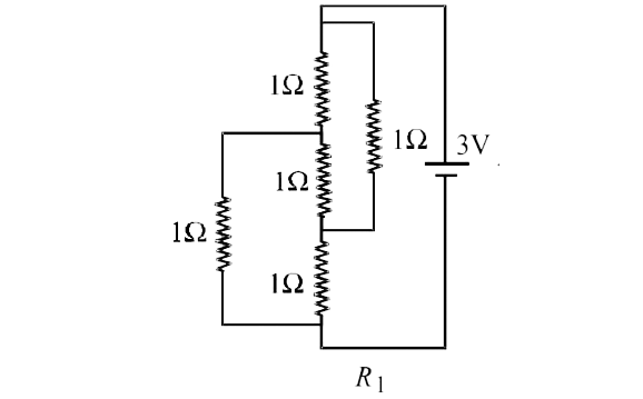
- Figure shows three resistor configurations R1,R2 and R3 connected to 3...
Text Solution
|
- For any three non-zero vectors r1,r2 and r3 .|(r1.r1,r1.r2,r1.r3),(r2....
Text Solution
|
- In Delta ABC, (r1+r2)(r2+r3)(r3+r1)=
Text Solution
|
- In Delta ABC, r3+ (r1 r2)/(r1+r2)=
Text Solution
|
- In DeltaABC,(r2(r3+r1))/sqrt(r1 r2+r2 r3+r3r1)=
Text Solution
|
- r1 (r2 + r3) / sqrt (r1 r2 + r2 r3 + r3 r1) = a అని రుజువు చేయండి.
Text Solution
|
- In an electric circuit three resistors R1,R2 and R3 are connected in s...
Text Solution
|
- If (r2-r1) (r3-r1) =2r2r3. show that A = 90 ^(@) (1-(r1)/( r2))...
Text Solution
|
- ( r1+ r2) (r2+r3) (r3+r1) =
Text Solution
|