
A
B
C
D
Text Solution
Verified by Experts
The correct Answer is:


Topper's Solved these Questions
Similar Questions
Explore conceptually related problems
CENGAGE PHYSICS ENGLISH-WAVE OPTICS-Linked Comprehension
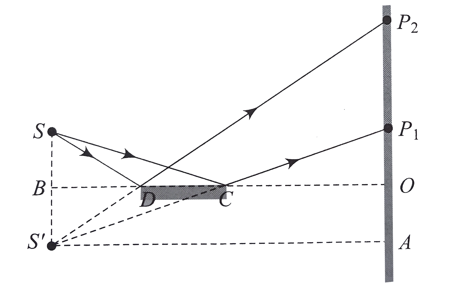
- The arrangement for a mirror experiment is shown in figure. S is a poi...
Text Solution
|
- The arrangement for a mirror experiment is shown in figure. S is a poi...
Text Solution
|
- The arrangement for a mirror experiment is shown in figure. S is a poi...
Text Solution
|
- Young's double-slit experiment setup with ligth of wavelength lambda =...
Text Solution
|
- Young's double-slit experiment setup with ligth of wavelength lambda =...
Text Solution
|
- Young's double-slit experiment setup with ligth of wavelength lambda =...
Text Solution
|
- An interference is observed due to two coherent sources S1 placed at o...
Text Solution
|
- An interference is observed due to two coherent sources S1 placed at o...
Text Solution
|
- The figure shows the interfernece pattern obtained in double slit expe...
Text Solution
|
- The figure shows the interfernece pattern obtained in double slit expe...
Text Solution
|
- The figure shows the interfernece pattern obtained in double slit expe...
Text Solution
|
- This interference film is used to measure the thickness of slides, pap...
Text Solution
|
- This interference film is used to measure the thickness of slides, pap...
Text Solution
|
- This interference film is used to measure the thickness of slides, pap...
Text Solution
|
- This interference film is used to measure the thickness of slides, pap...
Text Solution
|
- A block o plastic having a thin air cavity (whose thickenss is compara...
Text Solution
|
- A block o plastic having a thin air cavity (whose thickenss is compara...
Text Solution
|
- A block o plastic having a thin air cavity (whose thickenss is compara...
Text Solution
|
- In fig., light of wavelength lambda = 5000 Å is incident on the slits ...
Text Solution
|
- In fig., light of wavelength lambda = 5000 Å is incident on the slits ...
Text Solution
|