A
B
C
D
Text Solution
AI Generated Solution
The correct Answer is:


Topper's Solved these Questions
SOURCES OF MAGNETIC FIELD
CENGAGE PHYSICS ENGLISH|Exercise Exercise (integer)|7 VideosSOURCES OF MAGNETIC FIELD
CENGAGE PHYSICS ENGLISH|Exercise Archives (fill In The Blanks)|1 VideosSOURCES OF MAGNETIC FIELD
CENGAGE PHYSICS ENGLISH|Exercise Exercise (assertion-reasioning )|2 VideosRAY OPTICS
CENGAGE PHYSICS ENGLISH|Exercise DPP 1.6|12 VideosWAVE OPTICS
CENGAGE PHYSICS ENGLISH|Exercise Comprehension Type|14 Videos
Similar Questions
Explore conceptually related problems
CENGAGE PHYSICS ENGLISH-SOURCES OF MAGNETIC FIELD-Exercise (linked Comprehension)
- There exists a long conductor along z-axis carrying a current I0 along...
Text Solution
|
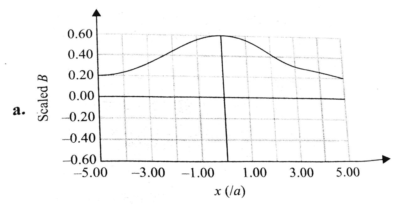
- Curves in the graph shown in Fig. give, as function of radius distance...
Text Solution
|
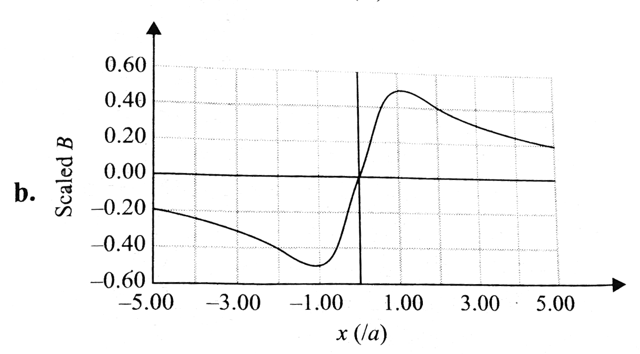
- Curves in the graph shown in Fig. give, as function of radius distance...
Text Solution
|
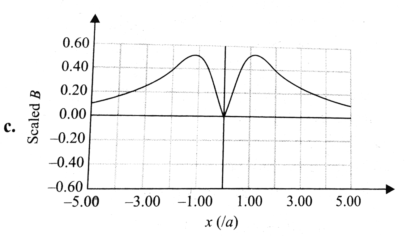
- Curves in the graph shown in Fig. give, as function of radius distance...
Text Solution
|
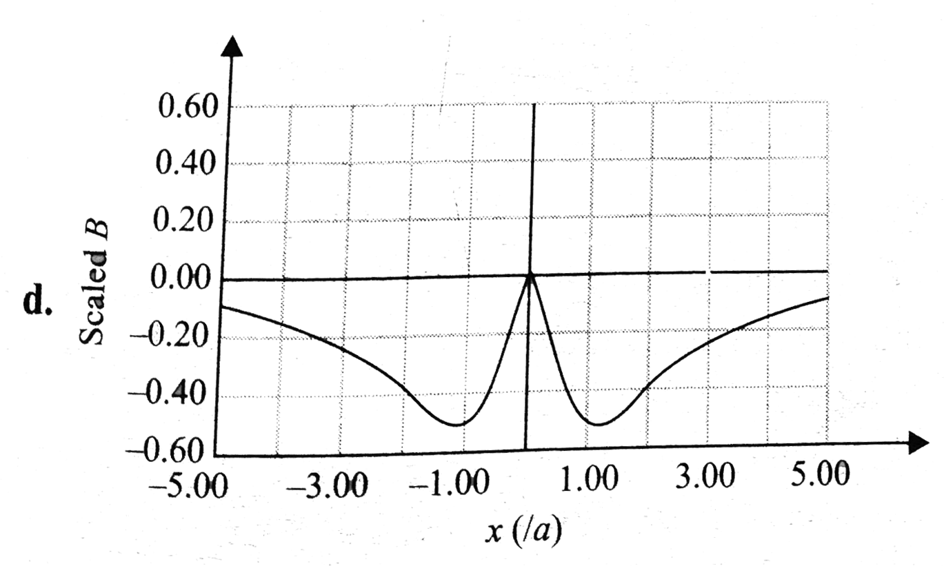
- Ampere's law provides us an easy way to calculate the magnetic field d...
Text Solution
|
- Ampere's law provides us an easy way to calculate the magnetic field d...
Text Solution
|
- Ampere's law provides us an easy way to calculate the magnetic field d...
Text Solution
|
- According to Biot-Savarat's law, magentic field due to a straight curr...
Text Solution
|
- According to Biot-Savarat's law, magentic field due to a straight curr...
Text Solution
|
- In Fig. the circular and the straight parts of the wire are made of sa...
Text Solution
|
- In Fig. the circular and the straight parts of the wire are made of sa...
Text Solution
|
- Two long, straight, parallel wires are 1.00m apart (as shown in Fig). ...
Text Solution
|
- Two long, straight, parallel wires are 1.00m apart (as shown in Fig). ...
Text Solution
|
- Two long, straight, parallel wires are 1.00m apart (as shown in Fig). ...
Text Solution
|
- Figure shows an end view of two long, parallel wires perpendicular to ...
Text Solution
|
- Figure shows an end view of two long, parallel wires perpendicular to ...
Text Solution
|
- Figure shows an end view of two long, parallel wires perpendicular to ...
Text Solution
|
- Repeat the above problem, but with the current in both wires shown in ...
Text Solution
|
- Repeat the above problem, but with the current in both wires shown in ...
Text Solution
|
- Repeat the above problem, but with the current in both wires shown in ...
Text Solution
|